KA7525BD Просмотр технического описания (PDF) - Fairchild Semiconductor
Номер в каталоге
Компоненты Описание
производитель
KA7525BD Datasheet PDF : 18 Pages
| |||
KA7525B
Operating Description
KA7525B is high performance, critical conduction, current-mode power factor controller specifically designed for use in off
line active preconverters with minimal external components. This device provides the necessary features required to
significantly enhance poor power factor loads by keeping the ac line current sinuosity and in phase with the line voltage.
KA7525B contains many of the building blocks and protection features that are employed in modern high performance current
mode power supply controllers. A description of each of the function blocks is given below.
START-UP
An Under Voltage Lockout comparator has been incorporated to guarantee that IC is fully functional before enable the output
stage. The positive power supply terminal (Vcc) is monitored by the UVLO comparator with the upper threshold set at 10V
and the lower threshold at 7.9V. In the stand-by mode, with Vcc at 9.5V, the required supply current is less than 0.2mA. This
large hysteresis and low start-up current allow the implementation of efficient bootstrap start-up techniques, making this
device ideally suited for wide range off-line preconverter applications.
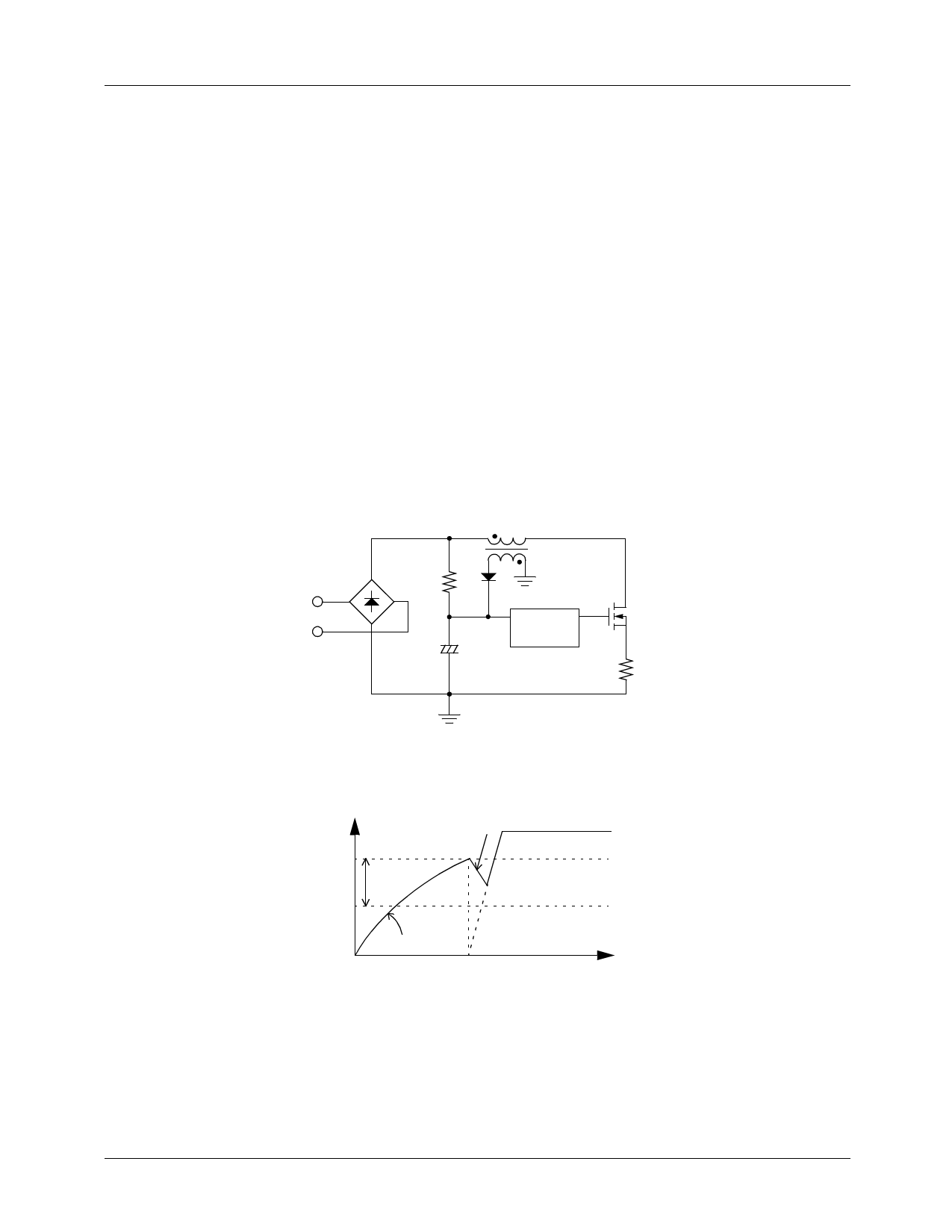
Fig.1.1 shows the start-up circuit. Circuit operation is as follows:
The start-up capacitor (Cst) is charged by current through start-up resistor (Rst) minus the start-up current drawn by the IC.
Once the capacitor voltage reaches the start-up threshold, the IC turns on, starting the switching of the MOSFET. The opera-
tion of the IC demands an increase in operating current which results in discharging the capacitor. Before the start-up capacitor
voltage is discharged below hysteresis voltage, the auxiliary winding voltage takes over as the supply voltage as shown in Fig.
1.2.
AC
input
Rst
+
Cst
DVcc
Vcc
Out
KA7525/BB
Figure 1.1 Start-up Circuit
Vcc
Vstart
Hysteresis
Cst discharges
Cst charges
from Rst
t
Figure 1.2 Start-up Capacitor Voltage
9
Share Link: 