IRS2980SPBF Просмотр технического описания (PDF) - International Rectifier
Номер в каталоге
Компоненты Описание
производитель
IRS2980SPBF Datasheet PDF : 18 Pages
| |||
IRS2980S
Application Information and Additional
Details
The IRS2980S is primarily intended for use in
Buck LED drivers operating with average current
regulation using hysteretic control. The circuit
topology uses a low side MOSFET referenced to
the 0V bus driven by a low side gate driver circuit
within the IRS2980S and an additional fast
recovery freewheeling diode. In order to minimize
switching losses the reverse recovery time of this
diode should be no more than 35nS. The
MOSFET should be selected for low capacitance
to reduce switching losses and low gate charge
(less than 25nC is recommended) to minimize
gate drive current. The LED load is referenced to
the DC bus and not 0V. The IRS2980S
incorporates floating high side current sense
inputs allowing the LED current to be sensed both
when the MOSFET is switched on and off. This
enables hysteretic operation, switching the
MOSFET off when the current rises above an
upper threshold and off when the current falls
below a lower threshold.
The current sense threshold Vcs is nominally
500mV with approximately 100mV of hysteresis
making the upper limit Vcs+50mV and the lower
limit Vcs-50mV. Some overshoot typically occurs
due to propagation delays and a small undershoot
is also possible. These vary depending on di/dt of
the ripple current, which is a function of input and
output voltage, inductor value and frequency as
well as RC filter values (RF and CF). The average
current is maintained at approximately the mid-
point over a wide input and output voltage range
due to the inherent accuracy of hysteretic control.
The LED output current is set by selecting the
value of the current sense resistor RCS. This is
determined by the formula:
operating conditions imposed by the input and
output voltages, output current and inductor value.
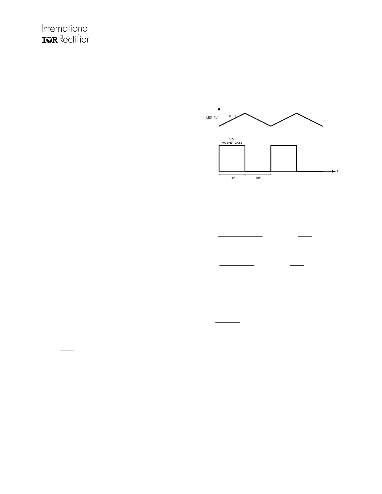
The following diagram shows the rise and fall of
the LED current as the MOSFET switches on and
off:
Figure 1: MOSFET gate drive and inductor/LED
current.
The following formulae model the operation of the
IRS2980S based Buck LED driver:
ton
≈ 0.2 ⋅ L ⋅ I LED
VBUS _ DC − VLED
+ RF
⋅CF
+
QG
0.18
+
tdr
toff
≈ 0.2 ⋅ L ⋅ I LED
VLED
+ RF ⋅CF
+
QG
0.26
+
tdf
f SW
=
ton
1
+ toff
(switching frequency)
d = ton (duty cycle)
ton + toff
RCS
=
VCS
I LED
Where ILED is the average LED output current.
The peak to peak ripple ∆ILED will be 20% of the
average LED current ILED due to the hysteretic
operation plus some additional ripple due to circuit
delays. These are caused mainly by the current
sense filter and MOSFET gate drive.
Since the IRS2980S uses hysteretic current
control to switch the Buck MOSFET on and off,
the LED current (which is equal to the inductor
current) is maintained between upper and lower
thresholds. Because of this the switching
frequency and duty cycle vary to meet the
Where,
RF and CF are the current sense filter
components,
L is the inductor value,
QG is the MOSFET gate charge,
tdr and tdf are propagation delays
(These values vary depending on circuit
conditions, tdr decreases with input voltage. tdf is
normally negligible. For a first order approximation
these terms may be ignored.)
www.irf.com
© 2011 International Rectifier
11
Share Link: 