IMP803 Просмотр технического описания (PDF) - IMP, Inc
Номер в каталоге
Компоненты Описание
производитель
IMP803 Datasheet PDF : 8 Pages
| |||
IMP803
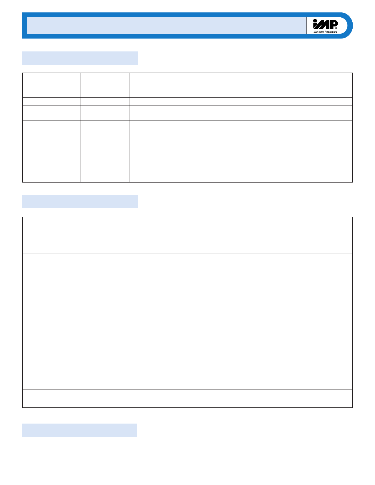
Pin Descriptions
Pin Number
1
2
3
4
5
6
Name
VDD
RSW-OSC
CS
LX
GND
VB
7
VA
8
REL-OSC
Function
Positive voltage supply for the IMP803. Inductor L may be connected here or to a
separate unregulated supply.
Switch-mode resistor pin. Switching frequency is determined by an external resistor, RSW.
Boost converter storage capacitor. The voltage across the EL lamp is equal to twice the
voltage at CS.
Connection to flyback inductance, L.
Ground pin.
EL lamp drive. The lamp is connected in a high-voltage bridge circuit with VB providing
the complementary connection to VA. The peak-to-peak AC voltage across the EL lamp is
thus two times VCS.
EL lamp drive. (See above)
The EL lamp oscillator frequency setting pin. The oscillator frequency is controlled
by external resistor REL.
External Components
External Component
Diode
Capacitor CS
Resistor REL
Resistor RSW
Inductor L
Lamp, RCL
Description and Selection Guide
Catch diode. A fast reverse recovery diode, with BV > 100, such as a 1N4148.
This is the high voltage capacitor that stores the inductive energy transferred through the
catch diode. A 100 volt capacitor between 10nF and 100nF is recommended.
The EL lamp oscillator frequency setting resistor. This resistor, connected between the
REL-OSC pin and VDD, provides an oscillator frequency inversely proportional to REL;
as REL increases, the EL lamp frequency decreases along with the current drawn by the lamp.
Lamp color is also determined by this frequency. A 2MΩ resistor between the REL-OSC pin and the
VDD supply results in a lamp frequency around 350Hz: a 1MΩ resistor will give ≈700Hz.
Switching Oscillator frequency setting resistor. The switching oscillator resistor is connected
between the RSW-OSC pin and the VDD supply. The switching frequency is inversely proportional
to the resistor value, dropping as the resistance increases.
The inductor provides the voltage boost needed by means of inductive “flyback”. The internal
MOSFET switch alternately opens and closes the ground connection for the inductor at the
LX pin. When this internal switch opens, the inductor potential will forward-bias the catch
diode and the current will pass through the storage capacitor CS, charging it to a high voltage.
Smaller inductors are preferred to prevent saturation. As the value of the inductor
increases (and the series DC resistance of the inductor decreases), the switching frequency
set by RSW should be increased to prevent saturation. In general, smaller value inductors that
can handle more current are more desirable when larger area EL lamps must be driven.
An external resistor (RCL) in series with the lamp will protect the output drivers from high transient
currents during lamp commutation.
High Voltages Present
The IMP803 generates high voltages and caution should
be exercised.
4
408-432-9100/www.impweb.com
© 2000 IMP, Inc.
Share Link: 