ICL3237 Просмотр технического описания (PDF) - Intersil
Номер в каталоге
Компоненты Описание
производитель
ICL3237 Datasheet PDF : 11 Pages
| |||
ICL3237
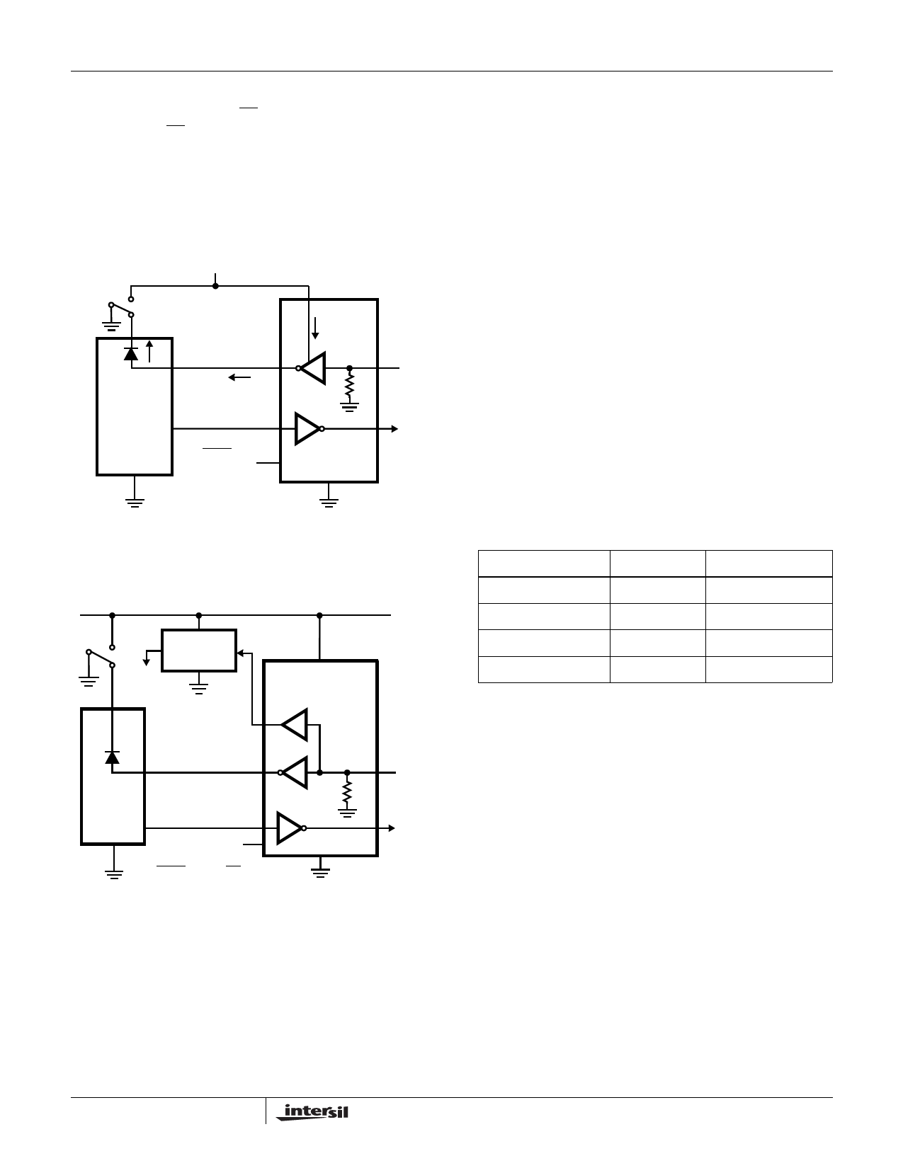
Receiver ENABLE Control
This device also features an EN input to control the receiver
outputs. Driving EN high disables all the inverting (standard)
receiver outputs placing them in a high impedance state.
This is useful to eliminate supply current, due to a receiver
output forward biasing the protection diode, when driving the
input of a powered down (VCC = GND) peripheral (see
Figure 2). The enable input has no effect on transmitter nor
monitor (ROUTB) outputs.
VCC
VCC
VCC
CURRENT
FLOW
POWERED
DOWN
UART
GND
VOUT = VCC
Rx
Tx
SHDN = GND
OLD
RS-232 CHIP
FIGURE 2. POWER DRAIN THROUGH POWERED DOWN
PERIPHERAL
VCC
TRANSITION
DETECTOR
TO
WAKE-UP
LOGIC
VCC
R1OUTB
RX
POWERED
DOWN
UART TX
VOUT = HI-Z
R1OUT
T1IN
ICL3237
R1IN
T1OUT
SHDN = GND, EN = VCC
FIGURE 3. DISABLED RECEIVERS PREVENT POWER DRAIN
MegaBaud Selection
In normal operating mode (MBAUD = GND), the ICL3237
transmitters guarantee a 250kbps data rate with worst-case
loads of 3kΩ in parallel with 1000pF. This provides
compatibility with PC-to-PC communication software, such
as Laplink™.
For higher speed serial communications, the ICL3237
features MegaBaud operation. In MegaBaud operating
mode (MBAUD = VCC), the ICL3237 transmitters guarantee
a 1Mbps data rate with worst-case loads of 3kΩ in parallel
with 250pF for 3.0V < VCC < 4.5V. For 5V ±10% operation,
the ICL3237 transmitters guarantee a 1Mbps data rate into
worst-case loads of 3kΩ in parallel with 1000pF.
Capacitor Selection
The charge pumps require 0.1µF capacitors for 3.3V
operation. For other supply voltages refer to Table 3 for
capacitor values. Do not use values smaller than those listed
in Table 3. Increasing the capacitor values (by a factor of 2)
reduces ripple on the transmitter outputs and slightly
reduces power consumption. C2, C3, and C4 can be
increased without increasing C1’s value, however, do not
increase C1 without also increasing C2, C3, and C4 to
maintain the proper ratios (C1 to the other capacitors).
When using minimum required capacitor values, make sure
that capacitor values do not degrade excessively with
temperature. If in doubt, use capacitors with a larger nominal
value. The capacitor’s equivalent series resistance (ESR)
usually rises at low temperatures and it influences the
amount of ripple on V+ and V-.
TABLE 3. REQUIRED CAPACITOR VALUES
VCC (V)
3.0 to 3.6
C1 (µF)
0.22
C2, C3, C4 (µF)
0.22
3.15 to 3.6
0.1
0.1
4.5 to 5.5
0.047
0.33
3.0 to 5.5
0.22
1.0
Power Supply Decoupling
In most circumstances a 0.1µF bypass capacitor is
adequate. In applications that are particularly sensitive to
power supply noise, decouple VCC to ground with a
capacitor of the same value as the charge-pump capacitor C1.
Connect the bypass capacitor as close as possible to the IC.
Transmitter Outputs when Exiting
Powerdown
Figure 4 shows the response of two transmitter outputs
when exiting powerdown mode. As they activate, the two
transmitter outputs properly go to opposite RS-232 levels,
with no glitching, ringing, nor undesirable transients. Each
transmitter is loaded with 3kΩ in parallel with 2500pF. Note
that the transmitters enable only when the magnitude of the
supplies exceed approximately 3V.
High Data Rates
The ICL3237 maintains the RS-232 ±5V minimum
transmitter output voltages even at high data rates. Figure 5
7
Laplink® is a registered trademark of Traveling Software.
Share Link: 