HV9901DB1 Просмотр технического описания (PDF) - Supertex Inc
Номер в каталоге
Компоненты Описание
производитель
HV9901DB1 Datasheet PDF : 2 Pages
| |||
F1
250mA
VIN
GND
R1
226kΩ
R2
8.25kΩ
VCC
5.0V @ 1mA
C5
1.0µF
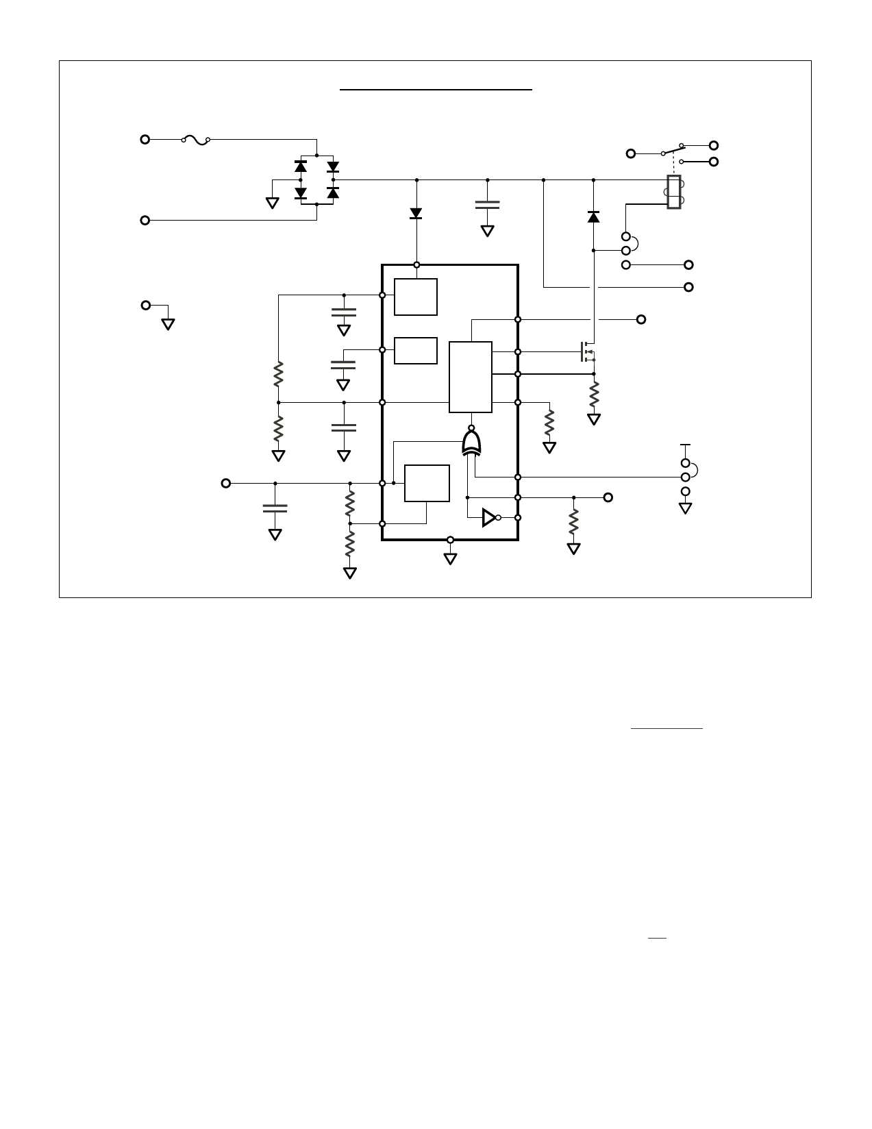
HV9901DB1 Schematic
D1
DF06
D2
C1
100nF
S1J
VIN
C2
4.7µF
VDD
VREF
C3
100nF
H/D
Int
Reg
VREF
PWM
C4
1.0µF
VCC
R3
374kΩ FB
R4
124kΩ
Aux
Reg
D3
ES1J
C
NC
NO
K1
NAIS JS1-5V
INT
EXT
RELAY
SYNC
SYNC
GT
Q1
CS
VN2450
RT
R5
11Ω
R6
1.21MΩ
POL
ENI
ENO
EN
R7
270kΩ
VCC
1
0
POL
Modifications
External Relay
Connect the coil of the external relay to the External Relay
terminals and move the Relay Selector shunt to the Ext
position.
Pull-in Current, Pull-in Time, and Hold Current
For use with other relays, these parameters may be changed
via resistors R1 and R2 and capacitor C4. Refer to the HV9901
data sheet for details.
Monitoring Relay Current
For the on-board relay, coil current may be monitored by
replacing the Relay Selector shunt with either a wire loop (for
current probe use) or with a low value sense resistor (for
voltage probe use). Remember that galvanic isolation is not
provided! See warnings on the first page.
Switching Frequency
To change the PWM switching frequency, change R6 according
to the following equation:
f PWM
= 3.23kHz +
21.8GHz ⋅ Ω
R6
This equation is valid for frequencies 25kHz and above. Be
advised that frequencies below 20kHz may cause the relay coil
to emit audible noise. And avoid higher frequencies that
approach the coils resonant frequency.
VCC
As provided, the HV9901DB1 supplies 5V for external circuitry.
Other volltages in the range 2.0V to 5.5V may be obtained by
changing R3. Current rating remains at 1mA.
VCC
= 1.25V1 +
R3
R4
Note that changing VCC also changes the Enable logic levels.
VEN (lo) < 0.3VCC
VEN (hi) > 0.7VCC
Share Link: 