HT7470 Просмотр технического описания (PDF) - Holtek Semiconductor
Номер в каталоге
Компоненты Описание
производитель
HT7470 Datasheet PDF : 7 Pages
| |||
HT7470
• Safety Timer Overflow: Internal event
counter has overflowed
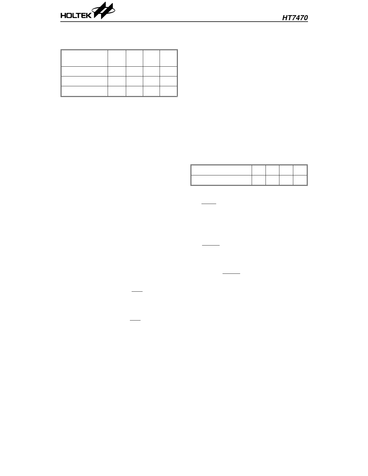
Charge rate
inputs
4C 2C 1C C/2
S1,S0
11 10 01 00
Charge Count 1200 2400 4800 9600
Time (min)
28 56 112 224
• Battery Maximum Voltage Protection
If any of the conditions described above oc-
cur the charge rate will switch to trickle
charge automatically.
Abnormal Charge Detection (Open, Short, Bat-
tery Damage)
The HT7470 can detect abnormal battery states
which include charge loop open or short, battery
high impedance or short. There is a precharge
procedure to pull-up the battery voltage for the
detection of abnormal states. The HT7470 pre-
charges the battery and looks for abnormal
states before the charge procedure begins. The
detection of abnormal states is always enabled
when the charge procedure is running. Any ab-
normal state will force the HT7470 to enter the
abnormal mode and display the corresponding
indicator or turn on the buzzer. In abnormal
mode the HT7470 stops charging until the ab-
normal battery is removed or the charge loop is
open.
A/D Converter
The battery voltage is read into the HT7470
through a 12 bit wide integral type A/D con-
verter. The resolution of the A/D converter is 68
µs/count (1MHz system clock).
Auto - Start and Reset Key (RST)
The HT7470 can detect whether the battery is
ready or not. When the battery has been de-
tected to be ready the HT7470 charge procedure
will run automatically. The RST pin is used for
system initialization. This reset pin has an in-
ternal pull-high resistor. In order to guarantee
all circuits are reset it is combined with an
external 0.1µF capacitor to provide an internal
reset pulse. If the charge loops is open the
HT7470 will enter the stand-by mode. In this
mode the HT7470 continues to detect whether
the battery is ready or not.
Charge and Discharge Inputs
Charge rate inputs: 4C, 2C, 1C, C/2
S1 and S0 are the charge rate inputs with inter-
nal pull-high resistors. The HT7470 adjusts the
internal parameters such as safety timer,
trickle charge duty cycle, and warm-up interval
by referring to these charge rate inputs to make
the system safe. These charge rate inputs are
determined by the external charge current. The
relationship between the inputs “S1,S0” and
charge rate are listed in the following table.
Charge rate inputs 4C 2C 1C C/2
S1,S0
11 10 01 00
Discharge Input: Discharge before charge pro-
cedure.
The DCHI pin is the discharge input with inter-
nal pull-high resistor. The user can force this
pin low to select the discharge function of the
HT7470.
Warm-Up Key
The WARM pin is the warm-up input with in-
ternal pull-high resistor and 20ms debounce
time.
The warm-up function is activated by a low
pulse on the WARM pin. The pulse width must
be larger than 20ms during the warm-up wait-
ing period.
Note that the discharge input will be inhibited
if the warm-up key is pushed.
The charge and discharge inputs are enabled
until the warm-up key is pushed or until the
end of the warm-up waiting period.
4
25th Aug ’94
Share Link: 