HT46R34 Просмотр технического описания (PDF) - Holtek Semiconductor
Номер в каталоге
Компоненты Описание
производитель
HT46R34 Datasheet PDF : 43 Pages
| |||
HT46R32/HT46R34
Arithmetic and Logic Unit - ALU
This circuit performs 8-bit arithmetic and logic opera-
tions. The ALU provides the following functions:
· Arithmetic operations - ADD, ADC, SUB, SBC, DAA
· Logic operations - AND, OR, XOR, CPL
· Rotation - RL, RR, RLC, RRC
· Increment and Decrement - INC, DEC
· Branch decision - SZ, SNZ, SIZ, SDZ ....
The ALU not only saves the results of a data operation but
also changes the status register.
Status Register - STATUS
This 8-bit register contains the zero flag (Z), carry flag
(C), auxiliary carry flag (AC), overflow flag (OV), power
down flag (PDF), and watchdog time-out flag (TO). It
also records the status information and controls the op-
eration sequence.
With the exception of the TO and PDF flags, bits in
the status register can be altered by instructions like
most other registers. Any data written into the status
register will not change the TO or PDF flag. In addi-
tion operations related to the status register may give
different results from those intended. The TO flag
can be affected only by system power-up, a WDT
time-out or executing the ²CLR WDT² or ²HALT² in-
struction. The PDF flag can be affected only by exe-
cuting the ²HALT² or ²CLR WDT² instruction or a
system power-up.
The Z, OV, AC and C flags generally reflect the status of
the latest operations.
In addition, on entering the interrupt sequence or exe-
cuting the subroutine call, the status register will not be
pushed onto the stack automatically. If the contents of
the status are important and if the subroutine can cor-
rupt the status register, precautions must be taken to
save it properly.
Interrupt
The devices provide an external interrupt, an internal
timer/event counter interrupt and an A/D converter inter-
rupt. The Interrupt Control Register, INTC, contains the
interrupt control bits to set the enable or disable and the
interrupt request flags.
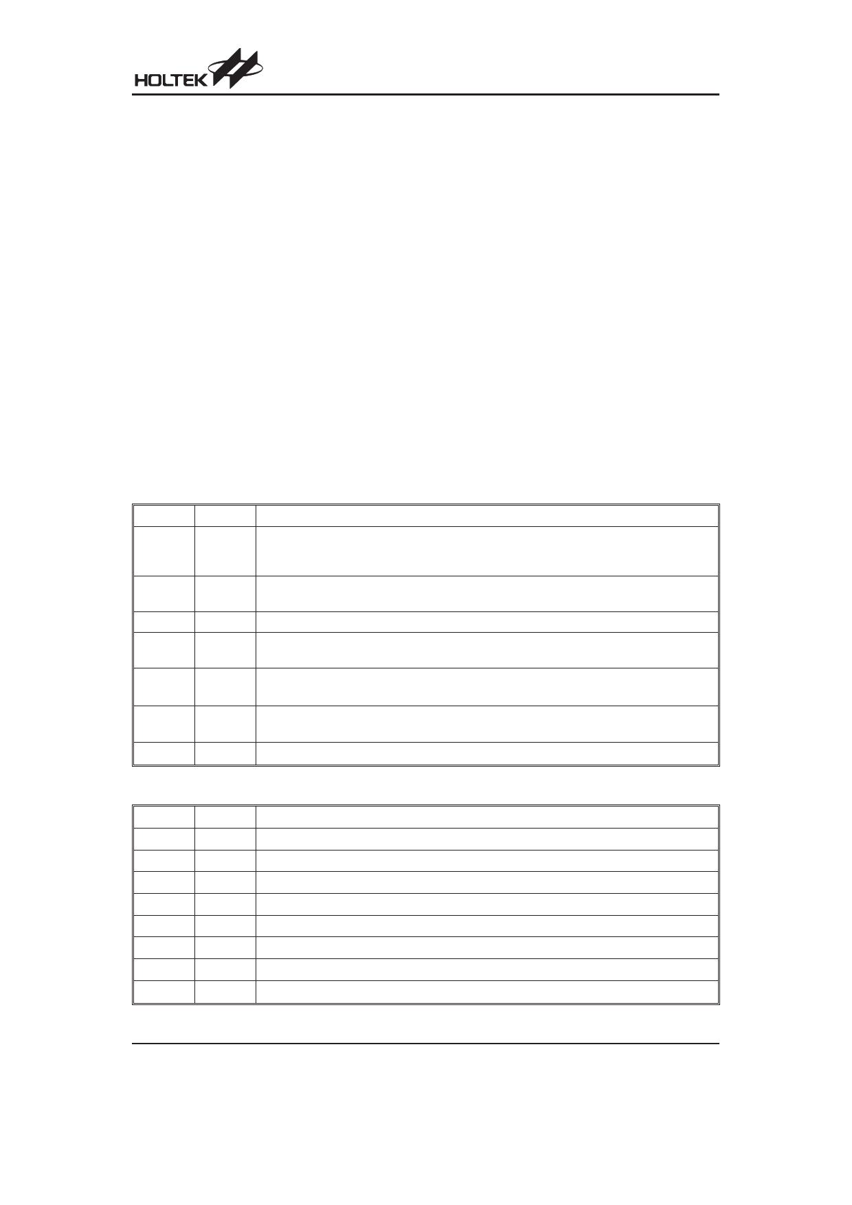
Bit No.
0
1
2
3
4
5
6, 7
Label
C
AC
Z
OV
PDF
TO
¾
Function
C is set if an operation results in a carry during an addition operation or if a borrow does not
take place during a subtraction operation, otherwise C is cleared. C is also affected by a ro-
tate through carry instruction.
AC is set if an operation results in a carry out of the low nibbles in addition or no borrow from
the high nibble into the low nibble in subtraction, otherwise AC is cleared.
Z is set if the result of an arithmetic or logic operation is zero, otherwise Z is cleared.
OV is set if an operation results in a carry into the highest-order bit but not a carry out of the
highest-order bit, or vice versa, otherwise OV is cleared.
PDF is cleared by a system power-up or executing the ²CLR WDT² instruction. PDF is set by
executing the ²HALT² instruction.
TO is cleared by a system power-up or executing the ²CLR WDT² or ²HALT² instruction. TO
is set by a WDT time-out.
Unused bit, read as ²0²
Status (0AH) Register
Bit No.
0
1
2
3
4
5
6
7
Label
EMI
EEI
ETI
EADI
EIF
TF
ADF
¾
Function
Controls the master (global) interrupt (1=enabled; 0=disabled)
Controls the external interrupt (1=enabled; 0=disabled)
Controls the Timer/Event Counter interrupt (1=enabled; 0=disabled)
Controls the A/D converter interrupt (1=enabled; 0=disabled)
External interrupt request flag (1=active; 0=inactive)
Internal Timer/Event Counter request flag (1=active; 0=inactive)
A/D converter request flag (1=active; 0=inactive)
Unused bit, read as ²0²
INTC (0BH) Register
Rev. 1.10
9
March 16, 2007
Share Link: 