HT46R34 Просмотр технического описания (PDF) - Holtek Semiconductor
Номер в каталоге
Компоненты Описание
производитель
HT46R34 Datasheet PDF : 43 Pages
| |||
HT46R32/HT46R34
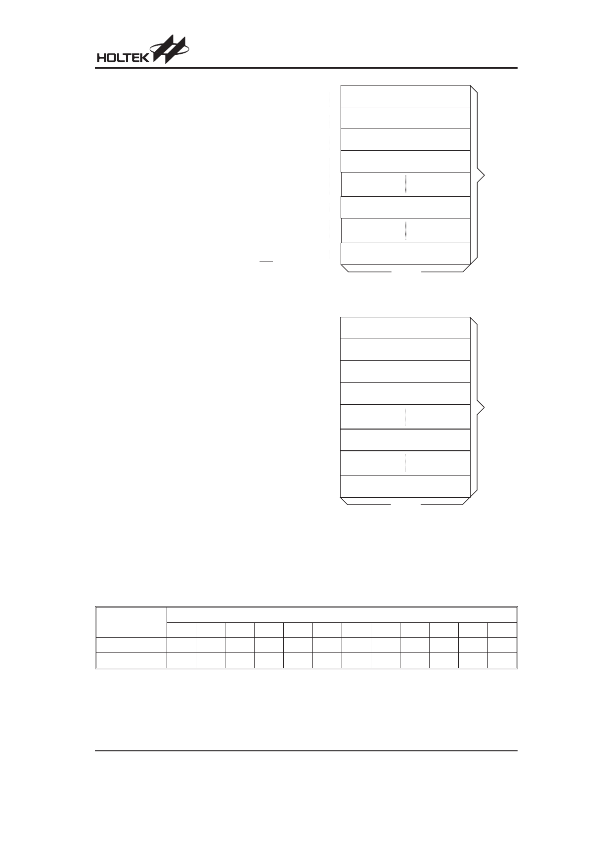
Program Memory - ROM
The program memory is used to store the program in-
structions which are to be executed as well as table data
and interrupt entries. It is structured into 2K´14 bits for
the HT46R32 device and 4K x 15 bits for the HT46R34
device, which can be addressed by both the program
counter and table pointer.
Certain locations in the program memory are reserved
for use by the reset and by the interrupt vectors.
· Location 000H
This vector is reserved for program initialisation. After
a device reset is initiated, the program will jump to this
location and begin execution.
· Location 004H
This vector is used by the external interrupt INT. If the
external interrupt pin on the device receives a low go-
ing edge, the program will jump to this location and be-
gin execution if the external interrupt is enabled and
the stack is not full.
· Location 008H
This vector is used by the Timer/Event Counter. If a
timer overflow occurs, the program will jump to this loca-
tion and begin execution if the timer interrupt is enabled
and the stack is not full.
· Location 00CH
This vector is used by the A/D converter. When an A/D
cycle conversion is complete, the program will jump to
this location and begin execution if the A/D interrupt is
enabled and the stack is not full.
· Table location
Any location in the Program Memory space can be
used as a look-up table. The instructions ²TABRDC
[m]² (the current page, 1 page=256 words) and
²TABRDL [m]² (the last page) transfer the contents of
the lower-order byte to the specified data memory,
and the higher-order byte to TBLH. Only the destina-
tion of the lower-order byte in the table is well-defined,
the other bits of the table word are transferred to the
lower portion of TBLH, and the remaining bits are read
as ²0². The Table Higher-order byte register (TBLH) is
read only. The table pointer (TBLP) is a read/write reg-
ister, which indicates the table location. Before ac-
cessing the table, the location must be placed in
TBLP. The TBLH register is read only and cannot be
000H
D e v ic e In itia liz a tio n P r o g r a m
004H
E x te r n a l In te r r u p t S u b r o u tin e
008H
T im e r /E v e n t C o u n te r In te r r u p t S u b r o u tin e
00C H
A /D C o n v e r te r In te r r u p t S u b r o u tin e
n00H
L o o k - u p T a b le ( 2 5 6 w o r d s )
nFFH
P ro g ra m
M e m o ry
700H
L o o k - u p T a b le ( 2 5 6 w o r d s )
7FFH
1 4 b its
N o te : n ra n g e s fro m 0 to 7
Program Memory - HT46R32
000H
D e v ic e In itia liz a tio n P r o g r a m
004H
E x te r n a l In te r r u p t S u b r o u tin e
008H
T im e r /E v e n t C o u n te r In te r r u p t S u b r o u tin e
00C H
A /D C o n v e r te r In te r r u p t S u b r o u tin e
P ro g ra m
M e m o ry
n00H
L o o k - u p T a b le ( 2 5 6 w o r d s )
nFFH
F00H
L o o k - u p T a b le ( 2 5 6 w o r d s )
FFFH
1 5 b its
N o te : n ra n g e s fro m 0 to F
Program Memory - HT46R34
restored. If the main routine and the ISR, Interrupt
Service Routine, both employ the table read instruc-
tion, the contents of the TBLH in the main routine are
likely to be changed by the table read instruction used
Instruction
TABRDC [m]
TABRDL [m]
Table Location
*11 *10 *9
*8
*7
*6
*5
*4
*3
*2
*1
*0
P11 P10 P9 P8 @7 @6 @5 @4 @3 @2 @1 @0
1
1
1
1 @7 @6 @5 @4 @3 @2 @1 @0
Table Location
Note:
*11~*0: Table location bits
P11~P8: Current program counter bits
@7~@0: Table pointer bits
For the HT46R32 device the Table address is 11 bits wide, i.e. from b10~b0, therefore the b11 column in the
table is not applicable.
Rev. 1.10
7
March 16, 2007
Share Link: 