HT46R34 Просмотр технического описания (PDF) - Holtek Semiconductor
Номер в каталоге
Компоненты Описание
производитель
HT46R34 Datasheet PDF : 43 Pages
| |||
HT46R32/HT46R34
Functional Description
Execution Flow
The system clock for the microcontroller is derived from
either a crystal or an RC oscillator. The system clock is
internally divided into four non-overlapping clocks. One
instruction cycle consists of four system clock cycles.
Instruction fetching and execution are pipelined in such
a way that a fetch takes an instruction cycle while de-
coding and execution takes the next instruction cycle.
However, the pipelining scheme causes each instruc-
tion to effectively execute in a cycle. If an instruction
changes the program counter, two cycles are required to
complete the instruction.
Program Counter - PC
The program counter controls the sequence in which the
instructions stored in program memory are executed
and whose contents specify full range of program mem-
ory.
After accessing a program memory word to fetch an in-
struction code, the contents of the program counter are
incremented by one. The program counter then points to
the memory word containing the next instruction code.
When executing a jump instruction, conditional skip ex-
ecution, loading PCL register, subroutine call, initial re-
set, internal interrupt, external interrupt or return from
subroutine, the PC manipulates the program transfer by
loading the address corresponding to each instruction.
The conditional skip is activated by instructions. Once
the condition is met, the next instruction, fetched during
the current instruction execution, is discarded and a
dummy cycle replaces it to get the proper instruction.
Otherwise proceed with the next instruction.
The lower byte of the program counter, PCL, is a read-
able and writeable register. Moving data into the PCL
performs a short jump. The destination will be within 256
locations.
When a control transfer takes place, an additional
dummy cycle is required.
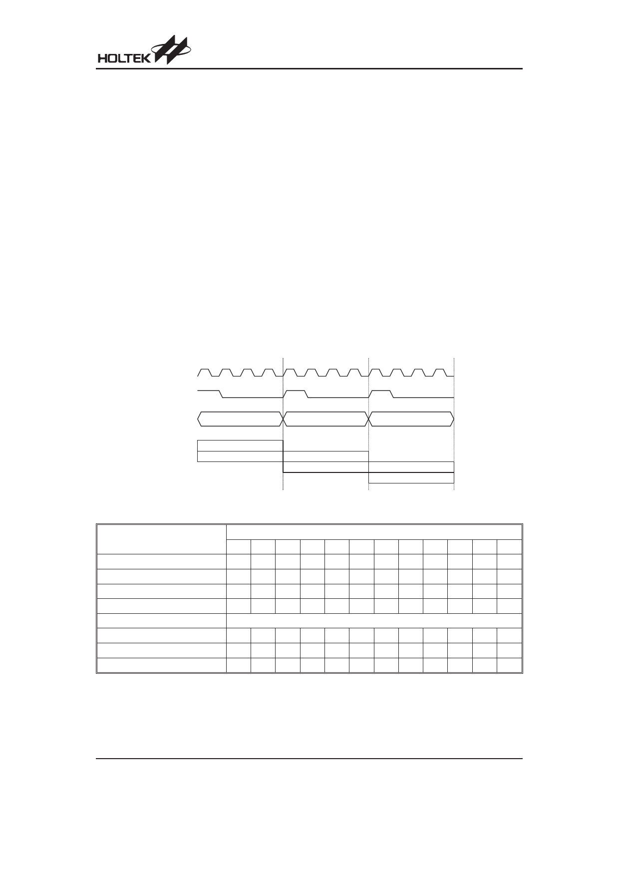
T1 T2 T3 T4 T1 T2 T3 T4 T1 T2 T3 T4
S y s te m C lo c k
O S C 2 ( R C o n ly )
PC
PC
PC +1
PC +2
F e tc h IN S T (P C )
E x e c u te IN S T (P C -1 )
F e tc h IN S T (P C + 1 )
E x e c u te IN S T (P C )
Execution Flow
F e tc h IN S T (P C + 2 )
E x e c u te IN S T (P C + 1 )
Mode
Initial Reset
External Interrupt
Timer/Event Counter Overflow
A/D Converter Interrupt
Skip
Loading PCL
Jump, Call Branch
Return from Subroutine
Program Counter
*11 *10 *9 *8 *7 *6 *5 *4 *3 *2 *1 *0
000000000000
000000000100
000000001000
000000001100
Program Counter+2
*11 *10 *9 *8 @7 @6 @5 @4 @3 @2 @1 @0
#11 #10 #9 #8 #7 #6 #5 #4 #3 #2 #1 #0
S11 S10 S9 S8 S7 S6 S5 S4 S3 S2 S1 S0
Program Counter
Note:
PC11~PC8: Current Program Counter bits
S11~S0: Stack register bits
#11~#0: Instruction Code bits
@7~@0: PCL bits
For the HT46R32 device the Program Counter is 11 bits wide, i.e. from b10~b0, therefore the b11 column in
the table is not applicable.
Rev. 1.10
6
March 16, 2007
Share Link: 