HT46C24 Просмотр технического описания (PDF) - Holtek Semiconductor
Номер в каталоге
Компоненты Описание
производитель
HT46C24 Datasheet PDF : 51 Pages
| |||
HT46R24/HT46C24
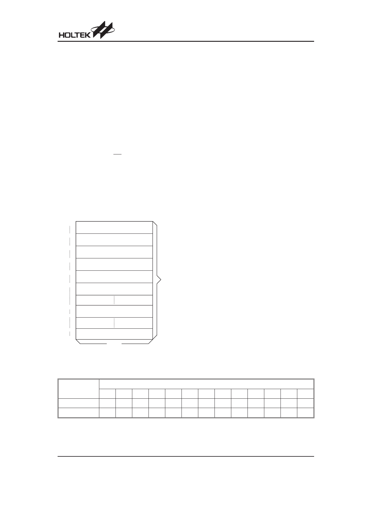
Program Memory - EPROM
The program memory (EPROM) is used to store the pro-
gram instructions which are to be executed. It also con-
tains data, table, and interrupt entries, and is organized
into 8192´16 bits which are addressed by the Program
Counter and table pointer.
Certain locations in the ROM are reserved for special
usage:
· Location 000H
Location 000H is reserved for program initialization.
After chip reset, the program always begins execution
at this location.
· Location 004H
Location 004H is reserved for the external interrupt
service program. If the INT input pin is activated, and
the interrupt is enabled, and the stack is not full, the
program begins execution at location 004H.
· Location 008H
Location 008H is reserved for the Timer/Event Coun-
ter 0 interrupt service program. If a timer interrupt re-
sults from a Timer/Event Counter 0 overflow, and if the
interrupt is enabled and the stack is not full, the pro-
gram begins execution at location 008H.
000H
D e v ic e In itia liz a tio n P r o g r a m
004H
E x te r n a l In te r r u p t S u b r o u tin e
008H
T im e r /E v e n t C o u n te r 0 In te r r u p t S u b r o u tin e
00C H
T im e r /E v e n t C o u n te r 1 In te r r u p t S u b r o u tin e
010H
A /D C o n v e rte r In te rru p t
014H
I2C B u s In te rru p t
P ro g ra m
M e m o ry
n00H
L o o k - u p T a b le ( 2 5 6 w o r d s )
nFFH
1F00H
1FFFH
L o o k - u p T a b le ( 2 5 6 w o r d s )
1 6 b its
N o te : n ra n g e s fro m 0 to 1 F
Program Memory
· Location 00CH
Location 00CH is reserved for the Timer/Event Coun-
ter 1 interrupt service program. If a timer interrupt re-
sults from a Timer/Event Counter 1 overflow, and if the
interrupt is enabled and the stack is not full, the pro-
gram begins execution at location 00CH.
· Location 010H
Location 010H is reserved for the A/D converter inter-
rupt service program. If an A/D converter interrupt re-
sults from an end of A/D conversion, and if the
interrupt is enabled and the stack is not full, the pro-
gram begins execution at location 010H.
· Location 014H
This area is reserved for the I2C Bus interrupt service
program. If the I2C Bus interrupt resulting from a slave
address is match or completed one byte of data trans-
fer, and if the interrupt is enable and the stack is not
full, the program begins execution at location 014H.
· Table location
Any location in the ROM can be used as a look-up ta-
ble. The instructions ²TABRDC [m]² (the current page,
page=256 words) and ²TABRDL [m]² (the last page)
transfer the contents of the lower-order byte to the
specified data memory, and the contents of the
higher-order byte to TBLH (Table Higher-order byte
register) (08H). Only the destination of the lower-order
byte in the table is well-defined; the other bits of the ta-
ble word are all transferred to the lower portion of
TBLH. The TBLH is read only, and the table pointer
(TBLP) is a read/write register (07H), indicating the ta-
ble location. Before accessing the table, the location
should be placed in TBLP. All the table related instruc-
tions require 2 cycles to complete the operation.
These areas may function as a normal ROM depend-
ing upon the users requirements
Stack Register - STACK
This is a special part of the memory which is used to
save the contents of the program counter (PC) only. The
stack is organized into 16 levels and is neither part of the
data nor part of the program space, and is neither read-
able nor writeable. The activated level is indexed by the
stack pointer (SP) and is neither readable nor writeable.
At the state of a subroutine call or an interrupt acknowl-
edgment, the contents of the program counter are
pushed onto the stack. At the end of the subroutine or an
interrupt routine, signaled by a return instruction (RET or
RETI), the program counter is restored to its previous
Instruction
TABRDC [m]
TABRDL [m]
*12 *11 *10 *9
P12 P11 P10 P9
1
1
1
1
Table Location
*8 *7 *6 *5 *4 *3 *2 *1 *0
P8 @7 @6 @5 @4 @3 @2 @1 @0
1 @7 @6 @5 @4 @3 @2 @1 @0
Table Location
Note: *12~*0: Table location bits
@7~@0: Table pointer bits
P12~P8: Current program counter bits
Rev. 2.00
7
March 2, 2006
Share Link: 