HT46C24 Просмотр технического описания (PDF) - Holtek Semiconductor
Номер в каталоге
Компоненты Описание
производитель
HT46C24 Datasheet PDF : 51 Pages
| |||
HT46R24/HT46C24
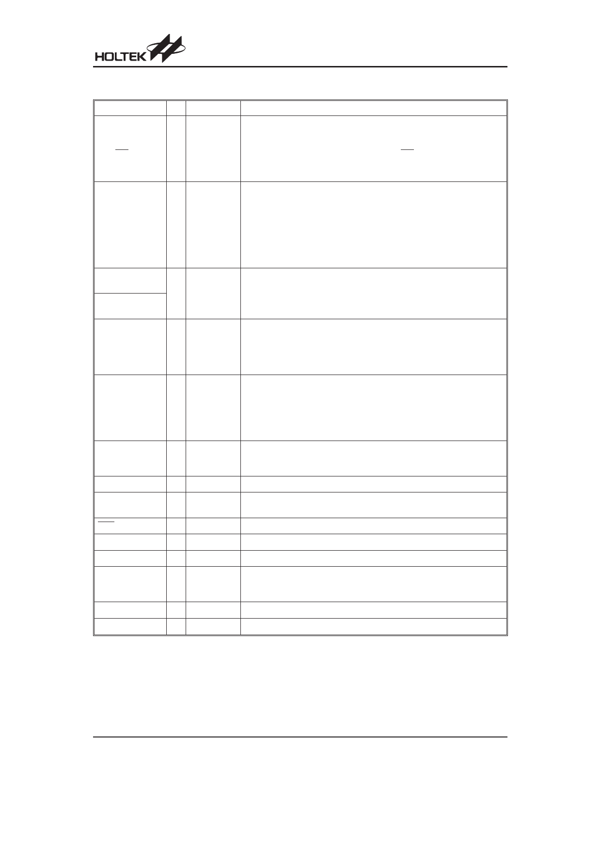
Pin Description
Pin Name
I/O Options
Description
PA0~PA2
PA3/PFD
PA4
PA5/INT
PA6/SDA
PA7/SCL
I/O
Pull-high
Wake-up
PA3 or PFD
I/O or Serial
Bus
Bidirectional 8-bit input/output port. Each bit can be configured as wake-up
input by option (bit option). Software instructions determine the CMOS out-
put or Schmitt trigger input with or without pull-high resistor (determined by
pull-high options: bit option). The PFD and INT are pin-shared with PA3
and PA5, respectively. Once the I2C Bus function is used, the internal reg-
isters related to PA6 and PA7 cannot be used.
PB0/AN0
PB1/AN1
PB2/AN2
PB3/AN3
PB4/AN4
PB5/AN5
PB6/AN6
PB7/AN7
Bidirectional 8-bits input/output port. Software instructions determine the
CMOS output, Schmitt trigger input with or without pull-high resistor (deter-
I/O Pull-high mined by pull-high option: bit option) or A/D input. Once a PB line is se-
lected as an A/D input (by using software control), the I/O function and
pull-high resistor are automatically disabled.
PC0~PC4
(28-pin package only)
I/O
PC0~PC7
(48-pin package only)
Pull-high
Bidirectional 8-bit input/output port. Software instructions determine the
CMOS output, Schmitt trigger input with or without pull-high resistor (deter-
mine by pull-high option: byte option).
PD0/PWM0
PD1/PWM1/TMR1 I/O
(28-pin package only)
Pull-high
PWM
Bidirectional 8-bit input/output port. Software instructions determine the
CMOS output, Schmitt trigger input with or without a pull-high resistor.
The PWM0 output function is pin-shared with PD0.
The PWM1 output function is pin-shared with PD1 and TMR1.
(determined by pull-high option: byte option)
PD0/PWM0
PD1/PWM1
PD2/PWM2
PD3/PWM3
I/O
PD4~PD7
(48-pin package only)
Pull-high
PWM
Bidirectional 8-bit input/output port. Software instructions determine the
CMOS output, Schmitt trigger input with or without a pull-high resistor (de-
termined by pull-high option: byte option). The PWM0/PWM1/PWM2/
PWM3 output function are pin-shared with PD0/PD1/PD2/PD3 (depending
on the PWM options).
PF0~PF7
I/O
(48-pin package only)
Pull-high
Bidirectional 8-bit input/output port. Software instructions determine the
CMOS output, Schmitt trigger input with or without pull-high resistor (deter-
mine by pull-high option: byte option).
TMR0
I
¾
Timer/Event Counter 0 Schmitt trigger input (without pull-high resistor)
TMR1
I
(48-pin package only)
¾
Timer/Event Counter 1 Schmitt trigger input (without pull-high resistor).
RES
I
¾
Schmitt trigger reset input, active low
VSS
¾
¾
Negative power supply, ground
VDD
¾
¾
Positive power supply
OSC1
OSC2
I
O
Crystal
or RC
OSC1 and OSC2 are connected to an RC network or a crystal (by options)
for the internal system clock. In the case of RC operation, OSC2 is the
output terminal for 1/4 system clock.
TEST1~3
I
¾
Test mode input pin it disconnects in normal operation.
NC
¾
¾
No connection
Rev. 2.00
3
March 2, 2006
Share Link: 