HT46R14-28 Просмотр технического описания (PDF) - Holtek Semiconductor
Номер в каталоге
Компоненты Описание
производитель
HT46R14-28 Datasheet PDF : 47 Pages
| |||
HT46R14
A.C. Characteristics
Symbol
fSYS
fTIMER
tWDTOSC
tRES
tSST
tINT
tAD
tADC
tADCS
tCOMP
Parameter
System Clock
Timer I/P Frequency
(TMR0/TMR1)
Watchdog Oscillator Period
External Reset Low Pulse Width
System Start-up Timer Period
Interrupt Pulse Width
A/D Clock Period
A/D Conversion Time
A/D Sampling Time
Comparator Response Time
Test Conditions
VDD
Conditions
¾ 2.2V~5.5V
¾ 3.3V~5.5V
¾ 2.2V~5.5V
¾ 3.3V~5.5V
3V
¾
5V
¾
¾
¾
¾
Power-up or Wake-up
from HALT
¾
¾
¾
¾
¾
¾
¾
¾
¾
¾
Note: *tSYS=1/fSYS
Ta=25°C
Min. Typ. Max. Unit
400
¾ 4000 kHz
400
¾ 8000 kHz
0
¾ 4000 kHz
0
¾ 8000 kHz
45
90
180
ms
32
65
130
ms
1
¾
¾
ms
¾
1024
¾
*tSYS
1
¾
¾
ms
1
¾
¾
ms
¾
76
¾
tAD
¾
32
¾
tAD
¾
¾
3
ms
Functional Description
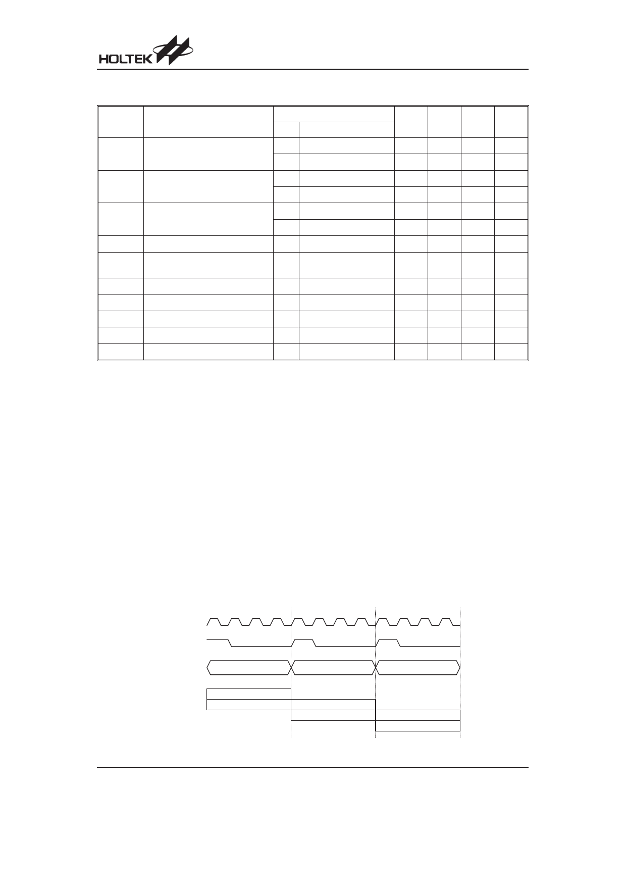
Execution Flow
The system clock for the microcontroller is derived from
either a crystal or an RC oscillator. The system clock is
internally divided into four non-overlapping clocks. One
instruction cycle consists of four system clock cycles.
Instruction fetching and execution are pipelined in such
a way that a fetch takes an instruction cycle while de-
coding and execution takes the next instruction cycle.
However, the pipelining scheme causes each instruc-
tion to effectively execute in a cycle. If an instruction
changes the program counter, two cycles are required to
complete the instruction.
Program Counter - PC
The program counter (PC) controls the sequence in
which the instructions stored in program PROM are exe-
cuted and its contents specify full range of program
memory.
After accessing a program memory word to fetch an in-
struction code, the contents of the program counter are in-
cremented by one. The program counter then points to the
memory word containing the next instruction code.
When executing a jump instruction, conditional skip ex-
ecution, loading PCL register, subroutine call, initial re-
set, internal interrupt, external interrupt or return from
subroutine, the PC manipulates the program transfer by
loading the address corresponding to each instruction.
T1 T2 T3 T4 T1 T2 T3 T4 T1 T2 T3 T4
S y s te m C lo c k
O S C 2 ( R C o n ly )
PC
PC
PC +1
PC +2
F e tc h IN S T (P C )
E x e c u te IN S T (P C -1 )
F e tc h IN S T (P C + 1 )
E x e c u te IN S T (P C )
Execution Flow
F e tc h IN S T (P C + 2 )
E x e c u te IN S T (P C + 1 )
Rev. 1.00
5
November 1, 2005
Share Link: 