HT1632C(2015) –Я—А–Њ—Б–Љ–Њ—В—А —В–µ—Е–љ–Є—З–µ—Б–Ї–Њ–≥–Њ –Њ–њ–Є—Б–∞–љ–Є—П (PDF) - Holtek Semiconductor
–Э–Њ–Љ–µ—А –≤ –Ї–∞—В–∞–ї–Њ–≥–µ
–Ъ–Њ–Љ–њ–Њ–љ–µ–љ—В—Л –Ю–њ–Є—Б–∞–љ–Є–µ
–њ—А–Њ–Є–Ј–≤–Њ–і–Є—В–µ–ї—М
HT1632C Datasheet PDF : 25 Pages
| |||
HT1632C
System Oscillator
The HT1632C system clock is used to generate the
time base clock frequency, LED-driving clock. The
clock may be sourced from an on-chip RC oscillator
(256kHz), or an external clock using the S/W setting.
The configuration of the system oscillator is as shown.
After the SYS DIS command is executed, the system
clock will stop and the LED duty cycle generator will
turn off. This command is, however, available only
for the on-chip RC oscillator. Once the system clock
stops, the LED display will become blank, and the
time base will also lose its function. The LED OFF
command is used to turn the LED duty cycle generator
off. After the LED duty cycle generator switches off
by issuing the LED OFF command, using the SYS
DIS command reduces power consumption, serving
as a system power down command. But if the external
clock source is chosen as the system clock, using the
SYS DIS command can neither turn the oscillator
off nor execute the power down mode. The crystal
oscillator option can be applied to connect an external
frequency source to the OSC pin. In this case, the
system fails to enter the power down mode, similar to
the case in the external clock source operation. At the
initial system power on, the HT1632C is in the SYS
DIS state.
O SC
E x te r n a l C lo c k S o u r c e
O n - c h ip R C O s c illa to r
256kH z
S y s te m
C lo c k
System Oscillator Configuration
LED Driver
The HT1632C has a 256 (32√Ч8) and 384 (24√Ч16)
pattern LED driver. It can be configured in a 32√Ч8 or
24√Ч16 pattern and common pad N-MOS open drain
output or P-MOS open drain output LED driver
using the S/W configuration. This feature makes the
HT1632C suitable for multiple LED applications. The
LED-driving clock is derived from the system clock.
The driving clock frequency is always 256kHz, an on-
chip RC oscillator frequency, or an external frequency.
The LED corresponding commands are summarized
in the table. The bold form of 1 0 0, namely 1 0
0, indicates the command mode ID. If successive
commands have been issued, the command mode ID
except for the first command will be omitted. The LED
OFF command turns the LED display off by disabling
the LED duty cycle generator. The LED ON command,
on the other hand, turns the LED display on by enabling
the LED duty cycle generator.
Name
LED OFF
LED ON
Commons Option
Command
Code
10000000010X
10000000011X
1000010abXXX
Function
Turn off LED outputs
Turn on LED outputs
ab=00: N-MOS open drain output and 8 common option
ab=01: N-MOS open drain output and 16 common option
ab=10: P-MOS open drain output and 8 common option
ab=11: P-MOS open drain output and 16 common option
Cascade Operation
For the cascade operation, the first IC is set to master mode and its SYNC and OSC pins are set to output pins. The
second IC is set to slave mode and its SYNC and OSC pins are set to input pins which are connected to the the
master IC. Please refer to the вА≥Cascade control flow chartвА≥ for detail settings.
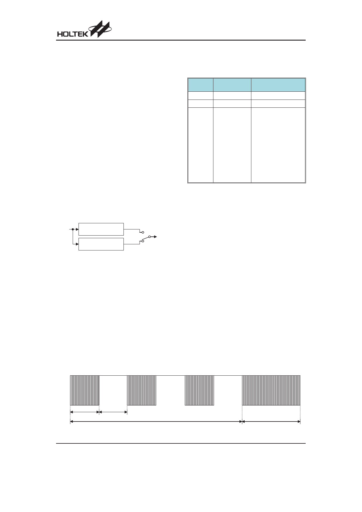
Blinker
The HT1632C has display blinking capabilities. The blink function generates all LED blinking. The blink rates is 0.25s
LED on and 0.25s LED off for one blinking period . This blinking function can be effectively performed by setting
the BLINK ON or BLINK OFF command.
LE D
T u rn O n
0 .2 5 s
T u rn O ff
0 .2 5 s
Rev. 1.60
B lin k O n
Example of Waveform for Blinker
7
B lin k O ff
August 19, 2015
Share Link: 