HI4-774T/883 Просмотр технического описания (PDF) - Intersil
Номер в каталоге
Компоненты Описание
производитель
HI4-774T/883 Datasheet PDF : 18 Pages
| |||
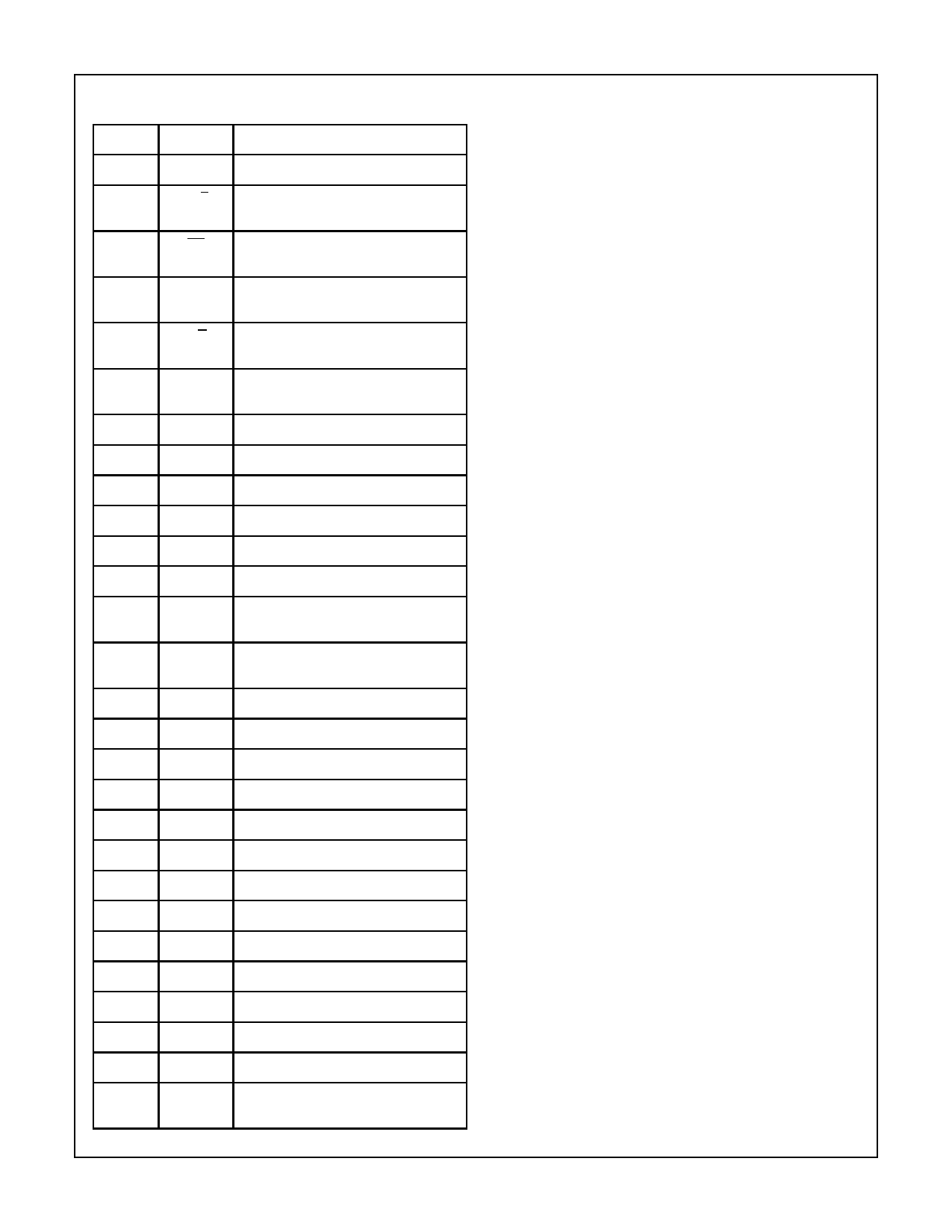
HI-574A, HI-674A, HI-774
Pin Descriptions
PIN
SYMBOL
DESCRIPTION
1
VLOGIC Logic supply pin (+5V)
2
12/8
Data Mode Select - Selects between
12-bit and 8-bit output modes.
3
CS
Chip Select - Chip Select high disables
the device.
4
AO
Byte Address/Short Cycle - See Table
1 for operation.
5
R/C
Read/Convert - See Table 1 for
operation.
6
CE
Chip Enable - Chip Enable low disables
the device.
7
VCC
Positive Supply (+12V/+15V)
8
REF OUT +10V Reference
9
AC
Analog Common
10
REF IN Reference Input
11
VEE
Negative Supply (-12V/-15V).
12
BIP OFF Bipolar Offset
13
10V Input 10V Input - Used for 0V to 10V and -5V
to +5V input ranges.
14
20V Input 20V Input - Used for 0V to 20V and -10V
to +10V input ranges.
15
DC
Digital Common
16
DB0
Data Bit 0 (LSB)
17
DB1
Data Bit 1
18
DB2
Data Bit 2
19
DB3
Data Bit 3
20
DB4
Data Bit 4
21
DB5
Data Bit 5
22
DB6
Data Bit 6
23
DB7
Data Bit 7
24
DB8
Data Bit 8
25
DB9
Data Bit 9
26
DB10 Data Bit 10
27
DB11 Data Bit 11 (MSB)
28
STS
Status Bit - Status high implies a
conversion is in progress.
Definitions of Specifications
Linearity Error
Linearity error refers to the deviation of each individual code
from a line drawn from “zero” through “full scale”. The point
used as “zero” occurs 1/2 LSB (1.22mV for 10V span) before
the first code transition (all zeros to only the LSB “on”). “Full
scale” is defined as a level 11/2 LSB beyond the last code tran-
sition (to all ones). The deviation of a code from the true straight
line is measured from the middle of each particular code.
The HI-X74(A)K and L grades are guaranteed for maximum
nonlinearity of ±1/2 LSB. For these grades, this means that an
analog value which falls exactly in the center of a given code
width will result in the correct digital output code. Values nearer
the upper or lower transition of the code width may produce the
next upper or lower digital output code. The HI-X74(A)J is
guaranteed to ±1 LSB max error. For this grade, an analog
value which falls within a given code width will result in either
the correct code for that region or either adjacent one.
Note that the linearity error is not user-adjustable.
Differential Linearity Error (No Missing Codes)
A specification which guarantees no missing codes requires
that every code combination appear in a monotonic increas-
ing sequence as the analog input level is increased. Thus
every code must have a finite width. For the HI-X74(A)K and L
grades, which guarantee no missing codes to 12-bit resolu-
tion, all 4096 codes must be present over the entire operating
temperature ranges. The HI-X74(A)J grade guarantees no
missing codes to 11-bit resolution over temperature; this
means that all code combinations of the upper 11 bits must be
present; in practice very few of the 12-bit codes are missing.
Unipolar Offset
The first transition should occur at a level 1/2 LSB above analog
common. Unipolar offset is defined as the deviation of the
actual transition from that point. This offset can be adjusted as
discussed on the following pages. The unipolar offset tempera-
ture coefficient specifies the maximum change of the transition
point over temperature, with or without external adjustment.
Bipolar Offset
Similarly, in the bipolar mode, the major carry transition
(0111 1111 1111 to 1000 0000 0000) should occur for an
analog value 1/2 LSB below analog common. The bipolar
offset error and temperature coefficient specify the initial
deviation and maximum change in the error over tempera-
ture.
Full Scale Calibration Error
The last transition (from 1111 1111 1110 to 1111 1111
1111) should occur for an analog value 11/2 LSB below the
nominal full scale (9.9963V for 10.000V full scale). The full
scale calibration error is the deviation of the actual level at
the last transition from the ideal level. This error, which is
typically 0.05 to 0.1% of full scale, can be trimmed out as
shown in Figures 2 and 3. The full scale calibration error
over temperature is given with and without the initial error
trimmed out. The temperature coefficients for each grade
indicate the maximum change in the full scale gain from the
initial value using the internal 10V reference.
6-961
Share Link: 