HCPL-0738 Просмотр технического описания (PDF) - HP => Agilent Technologies
Номер в каталоге
Компоненты Описание
производитель
HCPL-0738 Datasheet PDF : 8 Pages
| |||
the optocouplers at different
times. If this difference in propa-
gation delays is large enough, it
will determine the maximum rate
at which parallel data can be sent
through the optocouplers.
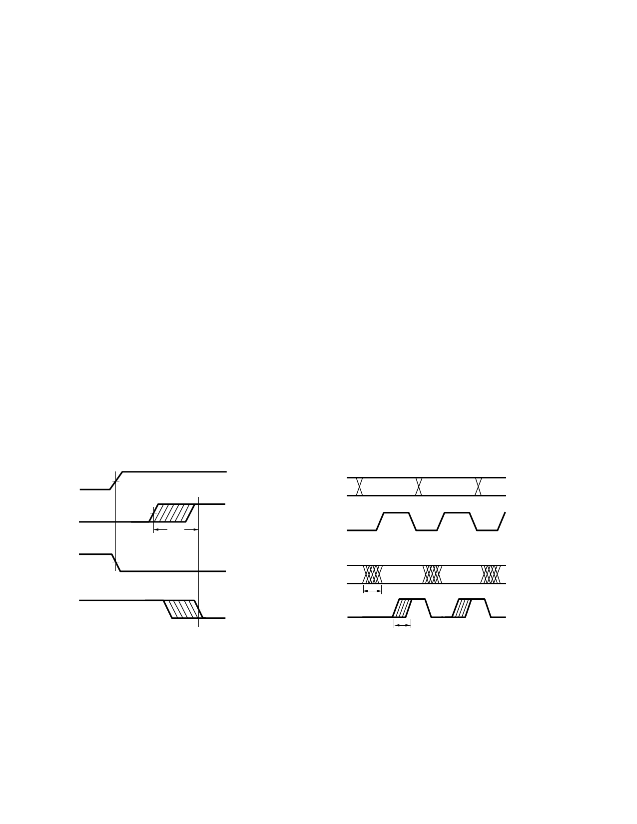
Propagation delay skew is defined
as the difference between the
minimum and maximum propaga-
tion delays, either tPLH or tPHL,
for any given group of
optocouplers which are operating
under the same conditions (i.e.,
the same supply voltage, output
load, and operating temperature).
As illustrated in Figure 8, if the
inputs of a group of optocouplers
are switched either ON or OFF at
the same time, tPSK is the differ-
ence between the shortest propa-
gation delay, either tPLH or tPHL,
and the longest propagation de-
lay, either tPLH or tPHL.
As mentioned earlier, tPSK can
determine the maximum parallel
data transmission rate. Figure 8
is the timing diagram of a typical
parallel data application with
both the clock and the data lines
being sent through optocouplers.
The figure shows data and clock
signals at the inputs and outputs
of the optocouplers. To obtain
the maximum data transmission
rate, both edges of the clock sig-
nal are being used to clock the
data; if only one edge were used,
the clock signal would need to be
twice as fast.
Propagation delay skew repre-
sents the uncertainty of where an
edge might be after being sent
through an optocoupler. Figure 7
shows that there will be
uncertainty in both the data and
the clock lines. It is important
that these two areas of uncer-
tainty not overlap, otherwise the
clock signal might arrive before
all of the data outputs have
settled, or some of the data out-
puts may start to change before
the clock signal has arrived.
From these considerations, the
absolute minimum pulse width
that can be sent through
optocouplers in a parallel appli-
cation is twice tPSK. A cautious
design should use a slightly
longer pulse width to ensure that
any additional uncertainty in the
rest of the circuit does not cause
a problem.
The tPSK specified optocouplers
offer the advantages of guaran-
teed specifications for propaga-
tion delays, pulse-width distortion
and propagation delay skew over
the recommended temperature,
and power supply ranges.
VI
50%
VO
2.5 V,
CMOS
tPSK
VI
50%
VO
2.5 V,
CMOS
Figure 7. Propagation delay skew waveform.
DATA
INPUTS
CLOCK
DATA
OUTPUTS
CLOCK
tPSK
tPSK
Figure 8. Parallel data transmission example.
7
Share Link: 