HAL1820UA-A Просмотр технического описания (PDF) - Micronas
Номер в каталоге
Компоненты Описание
производитель
HAL1820UA-A Datasheet PDF : 25 Pages
| |||
HAL 1820
DATA SHEET
2. Functional Description
2.1. General Function
The HAL1820 is a monolithic integrated circuit which
provides an output voltage proportional to the mag-
netic flux through the Hall plate and proportional to the
supply voltage (ratiometric behavior).
The external magnetic field component perpendicular
to the branded side of the package generates a Hall
voltage. The Hall IC is sensitive to magnetic north and
south polarity. This voltage is converted to a digital
value, processed in the Digital Signal Processing Unit
(DSP) according to the settings of the EEPROM regis-
ters, converted back to an analog voltage by a D/A
converter and buffered by a push-pull output transistor
stage. The function and the parameter for the DSP are
explained in Section 2.2. on page 8. Internal tempera-
ture compensation circuitry and the choppered offset
compensation enables operation over the full tempera-
ture range with minimal degradation in accuracy and
offset. The circuitry also rejects offset shifts due to
mechanical stress from the package. In addition, the
sensor IC is equipped with devices for overvoltage and
reverse-voltage protection at supply pin.
A LOCK register disables the programming of the
EEPROM memory. The register can not be reset by
the customer.
As long as the LOCK register is not set, the output
characteristic can be adjusted by programming the
EEPROM registers. The IC can be programmed via
VSUP line. After detecting a command, the sensor
reads or writes the memory and answers with a digital
signal on the output pin.
Output/Magnetic Field Polarity
Applying a south-pole magnetic field perpendicular to
the branded side of the package will increase the out-
put voltage (for Sensitivity < 0) from the quiescent (off-
set) voltage towards the supply voltage. A negative
magnetic field will decrease the output voltage. The
output logic will be inverted for sensitivity >0.
In addition HAL1820 features an internal error detec-
tion. The following error modes can be detected:
– Over-/underflow in adder or multiplier
– Over-/underflow in A/D converter
– Overtemperature detection
In case of an error the sensors output will be forced to
the lower error band. The error band is defined by
VDIAG (see Section 3.6. on page 14).
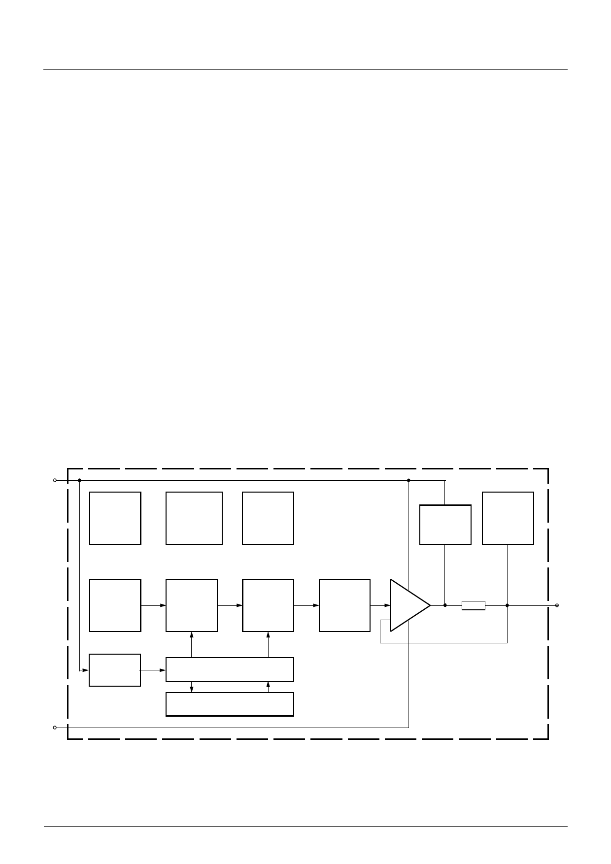
VSUP
Internally
stabilized
Supply and
Protection
Devices
Temperature
Dependent
Bias
Oscillator
Undervoltage
Detection
Protection
Devices
Switched
Hall Plate
A/D
Converter
Digital
Signal
Processing
D/A
Converter
Analog
Output
Programming
Interface
GND
EEPROM Memory
Lock Control
Fig. 2–1: HAL1820 block diagram
50
OUT
6
July 3, 2013; DSH000158_003EN
Micronas
Share Link: 