HAL115 Просмотр технического описания (PDF) - Micronas
Номер в каталоге
Компоненты Описание
производитель
HAL115 Datasheet PDF : 17 Pages
| |||
HAL114
4. Type Description
4.1. HAL 114
The HAL 114 is a unipolar switching sensor (see
Fig. 4–1).
The output turns low with the magnetic south pole on the
branded side of the package and turns high if the mag-
netic field is removed. The sensor does not respond to
the magnetic north pole on the branded side.
For correct functioning in the application, the sensor re-
quires only the magnetic south pole on the branded side
of the package.
Magnetic Features:
– switching type: unipolar
– typical BON: 21.1 mT at room temperature
– typical BOFF: 17.1 mT at room temperature
– operates with static magnetic fields and dynamic mag-
netic fields up to 20 kHz
Applications
The HAL 114 is the optimal sensor for applications with
one magnetic polarity such as:
– solid state switches,
– contactless solution to replace micro switches,
– position and end-point detection, and
– rotating speed measurement.
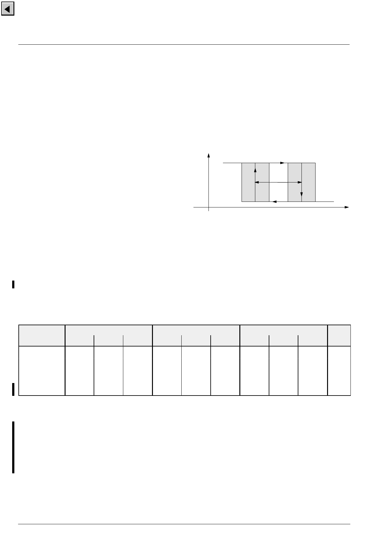
Output Voltage
VO
BHYS
VOL
0
BOFF
BON
B
Fig. 4–1: Definition of magnetic switching points for
the HAL 114
Magnetic Characteristics at TJ = –40 °C to +140 °C, VDD = 4.5 V to 24 V,
Typical Characteristics for VDD = 12 V
Magnetic flux density values of switching points.
Positive flux density values refer to the magnetic south pole at the branded side of the package.
Parameter
TJ
–40 °C
25 °C
100 °C
140 °C
Min.
7.5
7
6.3
6.1
On point BON
Typ.
Max.
21.5
36
21.1
34
19.9
31.5
19.4
31.3
Min.
Off point BOFF
Typ.
Max.
4.3
17.4
33.2
4
17.1
31.2
3.6
16.4
28.9
3.6
16.1
28.8
Hysteresis BHYS
Unit
Min.
Typ.
Max.
2.8
4.1
5
mT
2.8
4
4.5
mT
2.6
3.5
4
mT
2.2
3.3
4
mT
The hysteresis is the difference between the switching points BHYS = BON – BOFF
The magnetic limits given above refer to parts in the original packaging. Mechanical stress on the hall sensitive areas
on the chip surface may generate an additional magnetic offset, which can slightly change the magnetic switching
points. This behavior is a physical phenomenon and not a malfunction of the sensor. Mechanical stress on the hall plates
can be caused, for example, by overmoulding the plastic package or by wide range temperature changes like soldering
or operating the parts at extreme temperatures.
Please use a sensor of the HAL 5xx family if a robustness against mechanical stress is required.
10
Micronas
Share Link: 