HA-5330 Просмотр технического описания (PDF) - Intersil
Номер в каталоге
Компоненты Описание
производитель
HA-5330 Datasheet PDF : 5 Pages
| |||
HA-5330
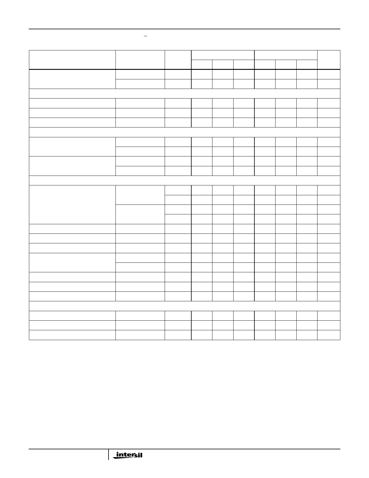
Electrical Specifications VSUPPLY = ±15V; S/H Control VIL = +0.8V (Sample): VIH = +2.0V (Hold); SIG GND = SUPPLY GND,
Unity Gain Configuration (Output tied to -Input), Unless Otherwise Specified (Continued)
PARAMETER
TEST
CONDITIONS
TEMP.
(oC)
HA-5330-2
MIN TYP MAX
HA-5330-5
MIN TYP MAX
UNITS
Total Output Noise, DC to 4MHz
TRANSIENT RESPONSE
Sample Mode
Hold Mode
-
230
-
-
230
-
µVRMS
25
-
190
-
-
190
-
µVRMS
Rise Time
Note 5
25
-
70
-
-
70
-
ns
Overshoot
Note 5
25
-
10
-
-
10
-
%
Slew Rate
Note 7
25
-
90
-
-
90
-
V/µs
DIGITAL INPUT CHARACTERISTICS
Input Voltage
VIH
VIL
Input Current
VIL = 0V
VIH = 5V
SAMPLE/HOLD CHARACTERISTICS
Full
2.0
-
-
2.0
-
-
V
Full
-
-
0.8
-
-
0.8
V
Full
-
10
40
-
10
40
µA
Full
-
10
40
-
10
40
µA
Acquisition Time
To 0.1%, Note 8
25
-
500
-
-
500
-
ns
Full
-
-
700
-
-
700
ns
To 0.01%, Note 8
25
-
650
-
-
650
-
ns
Full
-
-
900
-
-
900
ns
Aperture Time (Note 4)
25
-
20
-
-
20
-
ns
Effective Aperture Delay Time
25
-50
-25
0
-50
-25
0
ns
Aperture Uncertainty
25
-
0.1
-
-
0.1
-
ns
Droop Rate (Note 9)
25
-
0.01
-
-
0.01
-
µV/µs
Full
-
-
100
-
-
10
µV/µs
Hold Step Error
Note 10
25
-
0.5
-
-
0.5
-
mV
Hold Mode Settling Time
To 0.01%
25
-
100
200
-
100
200
ns
Hold Mode Feedthrough
20VP-P, 100kHz
POWER SUPPLY CHARACTERISTICS
Full
-
-88
-
-
-88
-
dB
Positive Supply Current
Full
-
18
22
-
18
24
mA
Negative Supply Current
Full
-
19
23
-
19
25
mA
Power Supply Rejection
Note 11
Full
86
100
-
86
100
-
dB
NOTES:
4. Derived from computer simulation only; not tested.
5. VI = 200mV Step; RL = 2kΩ; CL = 50pF.
6. Full power bandwidth based on slew rate measurement using:
slew rate enhancement circuitry.
FPBW = -2S---π-l-e--V-w---P---R-E----aA---t-K-e-- . Distortion of wave shape occurs beyond 100kHz due to
7. VO = 20V Step; RL = 2kΩ; CL = 50pF.
8. VO = 10V Step; RL = 2kΩ; CL = 50pF.
9. This parameter is measured at ambient temperature extremes in a high speed test environment. Consequently, steady state heating effects from
internal power dissipation are not included.
10. VIN = 0V; VIH = +3.5V; tR = 22ns (VIL to VIH). See graph.
11. Based on a 3V delta in each supply, i.e. 15V ±1.5VDC.
12. VOUT = 200mVP-P, RL = 2kΩ, CL = 50pF.
3
Share Link: 