GS9021A Просмотр технического описания (PDF) - Gennum -> Semtech
Номер в каталоге
Компоненты Описание
производитель
GS9021A Datasheet PDF : 26 Pages
| |||
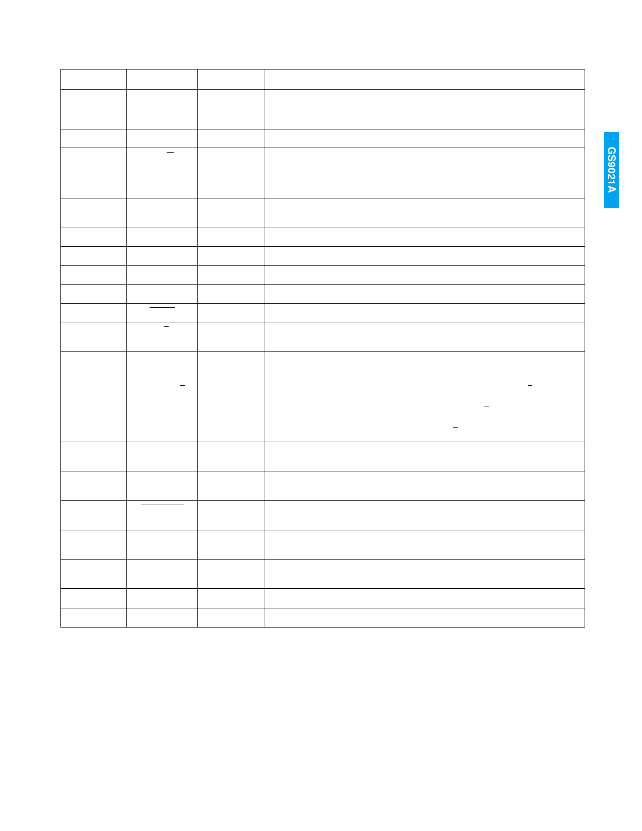
PIN DESCRIPTIONS
NUMBER
SYMBOL
28, 29
S[1:0]
30-34
35
FL[4:0]
F_R/W
36
FLAG_MAP
37-39, 42-48
49
50
51-53
54
55
DOUT[9:0]
V
H
F[2:0]
RESET
R/T
58
CRC_MODE
59
VBLANKS/L
60
BYPASS_EDH
61
LSB_TOP
62
BLANK_EN
63
FLYWDIS
64
CLIP_TRS
8, 26, 41, 57
9, 27, 40, 56
VDD
GND
TYPE
I/O
I/O
I
I
O
O
O
O
I
I
I
I
I
I
I
I
I
DESCRIPTION
Control bits which select whether FF, AP, or ANC EDH flags are active on the EDH
flag data port (FL[4:0]). In FLAG_MAP mode, the S[1:0] pins become outputs
(see device description).
EDH flag data port to allow access to the EDH flags.
Flag port read/write control. When HIGH, FL[4:0] are configured as outputs
allowing EDH flags to be read from the device. When LOW, FL[4:0] are
configured as inputs allowing EDH flags to be overwritten into the outgoing EDH
packet. In FLAG_MAP mode this pin must be set HIGH.
FLAG_MAP mode enable. When HIGH, FLAG_MAP mode is enabled. When
LOW, FLAG_MAP mode is disabled.
Parallel digital video data outputs.
Vertical sync indication.
Horizontal sync indication.
Field indication. F2 is the MSB.
Reset. When LOW, the internal control circuitry is reset.
Receive/Transmit mode select. When HIGH, the device operates in receive mode.
When LOW, the device operates in transmit mode.
CRC_MODE enable. When HIGH, CRC_MODE is enabled. When LOW,
CRC_MODE is disabled.
Vertical blanking interval control. For NTSC signals, when VBLANKS/L is set LOW
the 19 line blanking interval is selected and when set HIGH the 9 line blanking
interval is selected. For PAL D2 signals, when VBLANKS/L is set LOW the 17 line
blanking interval is selected and when set HIGH the 7 line blanking interval is
selected. For PAL component signals VBLANKS/L should be set LOW.
Bypass EDH control. When HIGH, the device allows the EDH packet to pass
through unaltered.
Data output LSB position control. When HIGH, the video data output bus is
reversed, placing the LSB at pin 48.
Blanking enable. When LOW, incoming data words are set to appropriate
blanking levels.
Flywheel disable. When HIGH, the internal flywheel is disabled. When LOW, the
internal flywheel is enabled.
Clip and TRS correction control. When HIGH, the TRS Blanking, ITU-R-601
clipping and TRS insertion features are enabled.
Power supply (nominally +5V).
Ground.
5 of 26
19983 - 1
Share Link: 