FOD2741A Просмотр технического описания (PDF) - Fairchild Semiconductor
Номер в каталоге
Компоненты Описание
производитель
FOD2741A Datasheet PDF : 15 Pages
| |||
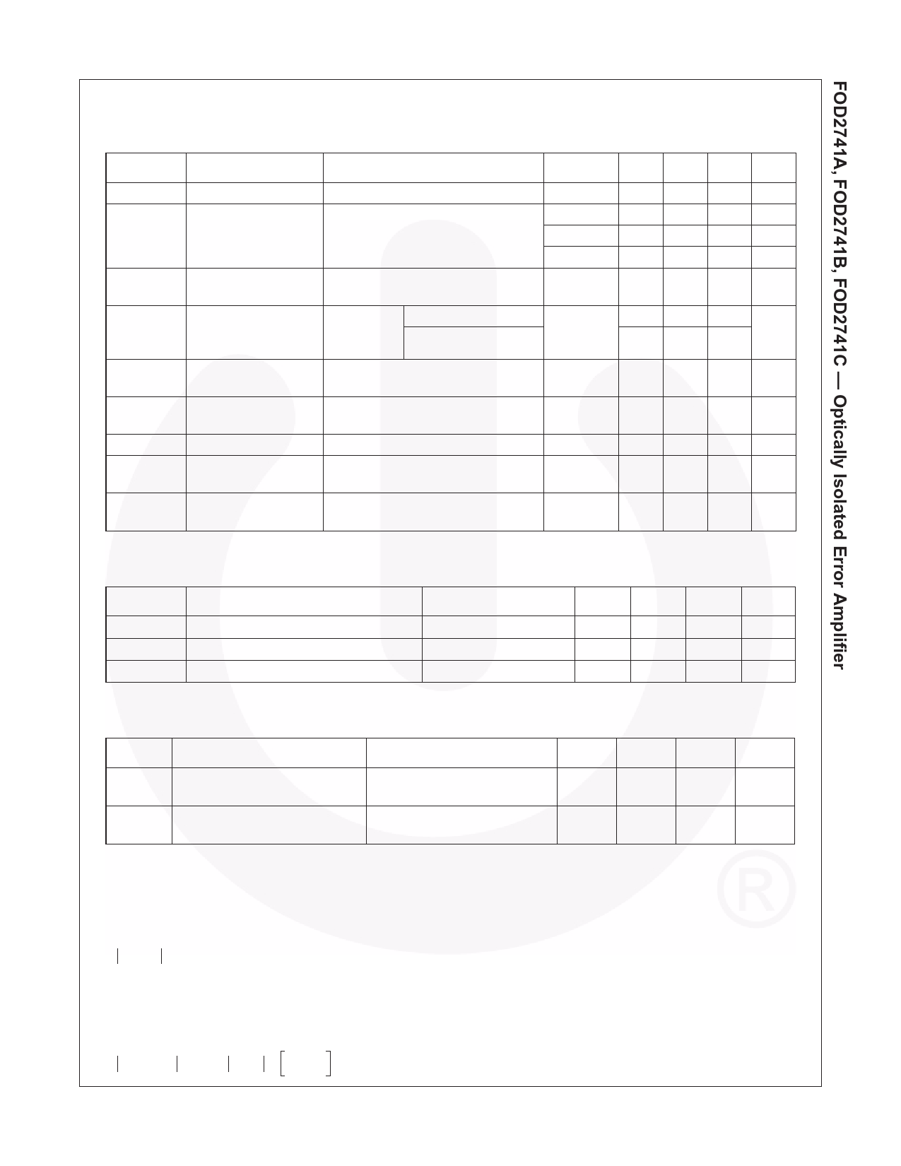
Electrical Characteristics (TA = 25°C unless otherwise specified)
Input Characteristics
Symbol
Parameter
Test Conditions
Device Min. Typ. Max. Unit
VF
V REF
LED Forward Voltage
Reference Voltage
ILED = 10mA, VCOMP = VFB (Fig.1)
ILED = 10mA, VCOMP = VFB
All
1.5 V
FOD2741A 2.482 2.495 2.508 V
FOD2741B 2.470 2.495 2.520 V
V REF
(4)
(DEV)
Deviation of VREF Over
TA = -25°C to +85°C
Temperature
FOD2741C 2.450 2.500 2.550 V
All
4.5 17 mV
∆VREF/ Ratio of VREF Variation ILED = 10mA ∆VCOMP = 10V to VREF
All
∆VCOMP to the Output of the
Error Amplifier
∆VCOMP = 36V to 10V
-1.0 -2.7 mV/V
-0.5 -2.0
IREF
Feedback Input
ILED = 10mA, R1 = 10kΩ (Fig. 3)
All
Current
IREF
(4)
(DEV)
Deviation of IREF Over
TA = -25°C to +85°C
All
Temperature
1.5
4
µA
0.4 1.2 µA
ILED (MIN)
I(OFF)
Minimum Drive Current VCOMP = VFB (Fig. 1)
Off-state Error
Amplifier Current
VLED = 37V, VFB = 0 (Fig. 4)
All
0.45 1.0 mA
All
0.05 1.0 µA
|ZOUT| Error Amplifier Output VCOMP = VREF, ILED = 1mA to 20mA,
All
impedance (5)
f ≥ 1.0 kHz
0.15 0.5 Ω
Output Characteristics
Symbol
Parameter
ICEO
BVECO
BVCEO
Collector Dark Current
Emitter-Collector Voltage Breakdown
Collector-Emitter Voltage Breakdown
Test Conditions
VCE = 10V (Fig. 5)
IE = 100µA
IC = 1.0mA
Min.
7
70
Typ.
Max.
50
Unit
nA
V
V
Transfer Characteristics
Symbol Parameter
CTR Current Transfer Ratio
VCE (SAT) Collector-Emitter Saturation
Voltage
Test Conditions
ILED = 10mA, VCOMP = VFB,
VCE = 5V (Fig. 6)
ILED = 10mA, VCOMP = VFB,
IC = 2.5mA (Fig. 6)
Min.
100
Typ.
Max.
200
Unit
%
0.4
V
Notes:
4. The deviation parameters VREF(DEV) and IREF(DEV) are defined as the differences between the maximum and
minimum values obtained over the rated temperature range. The average full-range temperature coefficient of the
reference input voltage, ∆VREF, is defined as:
∆VREF (ppm/°C)
=
{----V----R----E---F---(--D----E----V---)--/--V----R----E---F----(--T----A-----=------2---5----°--C-----)--}-----×----1----0---6-
∆TA
where ∆TA is the rated operating free-air temperature range of the device.
5. The dynamic impedance is defined as |ZOUT| = ∆VCOMP / ∆ILED. When the device is operating with two external
resistors (see Figure 2), the total dynamic impedance of the circuit is given by:
ZOUT, TOT = ∆--∆---V-I- ≈ ZOUT ×
1 + R-----1--
R2
©2004 Fairchild Semiconductor Corporation
FOD2741A, FOD2741B, FOD2741C Rev. 1.0.1
4
www.fairchildsemi.com
Share Link: 