FM301B Просмотр технического описания (PDF) - Willas Electronic Corp.
Номер в каталоге
Компоненты Описание
производитель
FM301B Datasheet PDF : 2 Pages
| |||
3.0 Amp Glass Passivated Super Fast Rectifiers - 50~1000Volts
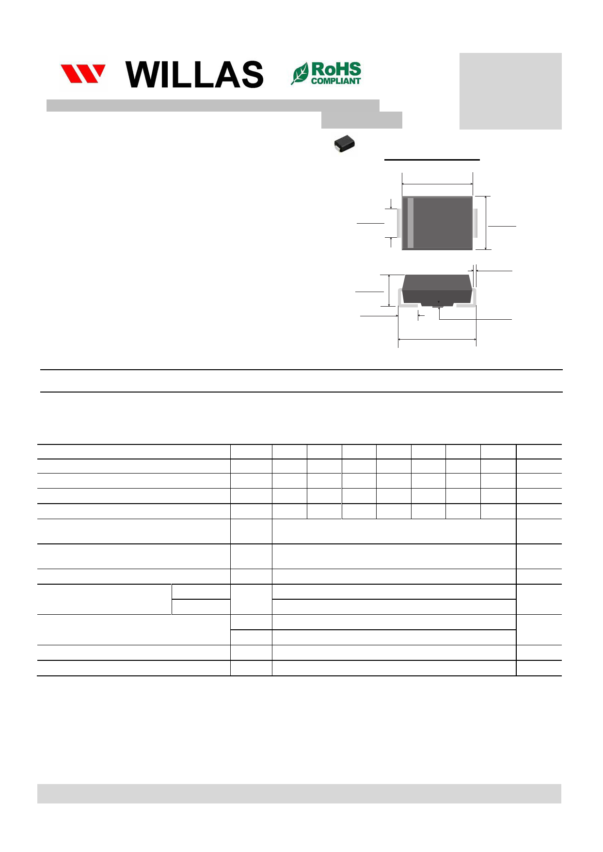
SMB Package
FM301%
THRU
FM307%
Features
Glass Passivated Chip
Ideal for surface mounted applications
Low leakage current
Metallurgic ally bonded construction
Moisture Sensitivity Level 1
RoHS product for packing code suffix “G”
Halogen free product for packing code suffix “H”
SMB(DO-214AA)
.191(4.85)
.160(4.06)
.086(2.20)
.075(1.91)
.115(3.94)
.130(3.30)
Mechanical Date
Case: Molded Plastic, SMB(DO214AA)
Epoxy: UL 94V-0 Rate Flame Retardant
Lead: Solderable per MIL-STD-202,
method 208 guaranteed
Polarity: Color band denotes cathode end
Mounting Position: Any
W eight: 0.004 ounce, 0.104 gram (Approximate)
.096(2.44)
.083(2.13)
.012(0.30)
.006(0.15)
.060(1.52)
.029(0.75)
.008(2.03)
.001(0.02)
.220(5.59)
.199(5.05)
Dimensions in inches and (millimeters)
MAXIMUM RATINGS AND ELECTRONICAL CHARACTERISTICS
Ratings at 25℃ ambient temperature unless otherwise specified.
Single phase half wave, 60Hz, resistive of inductive load.
For capacitive load, derate current by 20%
RATING
SYMBOLS FM301B FM302B FM303B FM304B FM305B FM306B FM307B
Marking code
3B1
3B2
3B3
3B4
3B5
3B6
3B7
Maximum Recurrent Peak Reverse Voltage
Maximum RMS Voltage
Maximum DC Blocking Voltage
Maximum Average Forward rectifier Current
0.375” (9.5mm) Lead length at Fig.1
VRRM
VRM S
VDC
IF(AV)
50
100
200
400
600
800 1000
35
70
140
280
420
560
700
50
100
200
400
600
800 1000
3.0
Peak Forward Surge Current 8.3 ms single half sine-wave
superimposed on rated load (JEDEC method)
IFSM
100
Maximum Instantaneous Forward Voltage at 3.0A DC
VF
1.1
Maximum DC Reverse Current at
@ Ta=25℃
5.0
Rated DC Blocking Voltage
@ Ta=100℃
IR
100
Typical Thermal Resistance (Note 2 )
Typical Junction Capacitance(Note 1)
Operating and Storage Temperature Range
RθJA
RθJC
CJ
TJ ,TSTG
40
15
60
-55 ~ 150
UNITS
Volts
Volts
Volts
Amps
Amps
Volts
μA
℃/W
pF
℃
Notes:
1. Measured at 1MHz and applied reverse voltage of 4.0VDC.
2. Thermal Resistance junction to ambient, 10.0*10.0 mm2 copper pads to each terminal.
Thermal Resistance junction to case, 10.0*10.0 mm2 copper pads to each terminal.
2013-01
WILLAS ELEECTRONIC CORP.
Share Link: 