TDA7381(1999) Просмотр технического описания (PDF) - STMicroelectronics
Номер в каталоге
Компоненты Описание
производитель
TDA7381 Datasheet PDF : 10 Pages
| |||
TDA7381
OUTPUT MISCONNECTIONS (OUT-GND &
OUT-Vs shorts)
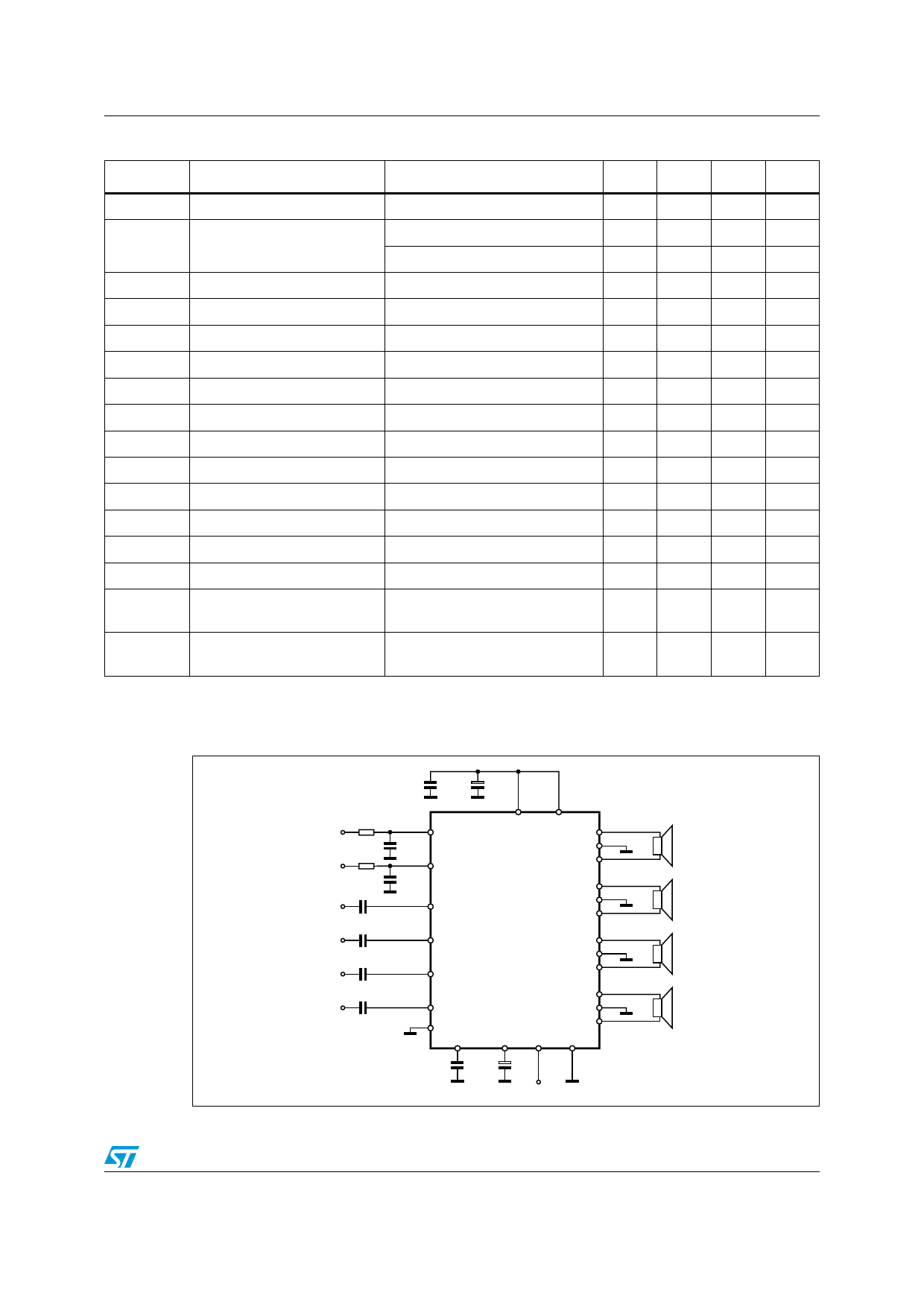
Diagnostics information is available across an
open collector output located at pin 25 (fig. 4)
through a current sinking whenever at least one
of the above events is recognized.
Among them, the CLIPPING DETECTOR acts in
a way to output a signal as soon as one or more
power transistors start being saturated.
As a result, the clipping-related signal at pin 25
Figure 4: Diagnostics circuit.
Figure 5: Clipping Detection Waveforms.
25
R
Vpin 25
VREF
TTDDAA77338815
D95AU303
Figure 6: Diagnostics Waveforms.
ST-BY PIN
VOLTAGE
MUTE PIN
VOLTAGE
Vs
OUTPUT
WAVEFORM
takes the form of pulses, which are perfectly syn-
cronized with each single clipping event in the
music program and reflect the same duration time
(fig. 5). Applications making use of this facility
usually operate a filtering/integration of the pulses
train through passive R-C networks and realize a
volume (or tone bass) stepping down in associa-
tion with microprocessor-driven audioprocessors.
The maximum load that pin 25 can sustain is
1KΩ.
Due to its operating principles, the clipping detec-
t
t
t
Vpin 25
WAVEFORM
D95AU304
t
CLIPPING
SHORT TO GND THERMAL
OR TO Vs
PROXIMITY
7/10
Share Link: 