FAN7602C Просмотр технического описания (PDF) - Fairchild Semiconductor
Номер в каталоге
Компоненты Описание
производитель
FAN7602C Datasheet PDF : 19 Pages
| |||
Application Information
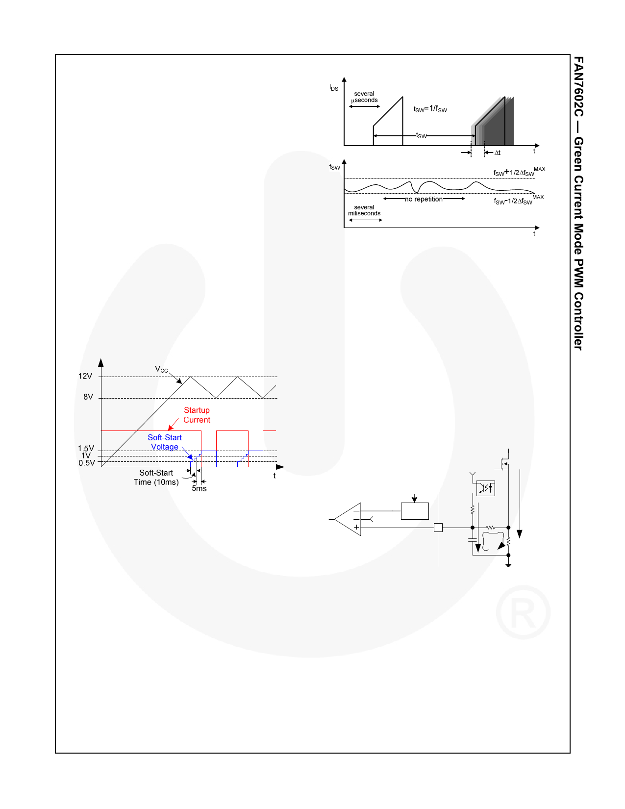
1. Startup Circuit and Soft-Start Block
The FAN7602C contains a startup switch to reduce the
power loss of the external startup circuit of the
conventional PWM converters. The internal startup
circuit charges the VCC capacitor with 0.9mA current
source if the AC line is connected. The startup switch is
turned off 15ms after IC starts up, as shown in Figure 19.
The soft-start function starts when the VCC voltage
reaches the start threshold voltage of 12V and ends
when the internal soft-start voltage reaches 1V. The
internal startup circuit starts charging the VCC capacitor
again if the VCC voltage is lowered to the minimum
operating voltage, 8V. The UVLO block shuts down the
output drive circuit and some blocks to reduce the IC
operating current and the internal soft-start voltage
drops to zero. If the VCC voltage reaches the start
threshold voltage, the IC starts switching again and the
soft-start block works as well.
During the soft-start, pulse-width modulated (PWM)
comparator compares the CS/FB pin voltage with the
soft-start voltage. The soft-start voltage starts from 0.5V
and the soft-start ends when it reaches 1V and the soft-
start time is 10ms. The startup switch is turned off when
the soft-start voltage reaches 1.3V.
Figure 20. Frequency Fluctuation Waveform
3. Current Sense and Feedback Block
The FAN7602C performs the current sensing for the
current mode PWM and the output voltage feedback
with only one pin, pin 3. To achieve the two functions
with one pin, an internal LEB (leading-edge blanking)
circuit to filter the current sense noise is not included
because the external RC filter is necessary to add the
output voltage feedback information and the current
sense information.
Figure 21 shows the current sense and feedback circuits.
RS is the current sense resistor to sense the switch
current. The current sense information is filtered by an
RC filter composed of RF and CF. According to the
output voltage feedback information, IFB charges or
stops charging CF to adjust the offset voltage. If IFB is
zero, CF is discharged through RF and RS to lower the
offset voltage.
Figure 19. Startup Current and VCC Voltage
2. Oscillator Block
The oscillator frequency is set internally and FAN7602C
has a random frequency fluctuation function.
Fluctuation of the switching frequency of a switched
power supply can reduce EMI by spreading the energy
over a wider frequency range than the bandwidth
measured by the EMI test equipment. The amount of
EMI reduction is directly related to the range of the
frequency variation. The range of frequency variation is
fixed internally; however, its selection is randomly
chosen by the combination of external feedback voltage
and internal free-running oscillator. This randomly
chosen switching frequency effectively spreads the EMI
noise nearby switching frequency and allows the use of
a cost-effective inductor instead of an AC input line filter
to satisfy the world-wide EMI requirements.
PWM
Comparator
PWM+
Soft-Start
Plimit
Offset
Power
Limit
VCC
RFB
CS/FB
3
CF
IFB
RF
Isw
RS
Figure 21. Current Sense and Feedback Circuits
Figure 22 shows typical voltage waveforms of the CS/FB
pin. The current sense waveform is added to the offset
voltage, as shown in the Figure 22. The CS/FB pin
voltage is compared with PWM that is 1V - Plimit offset.
If the CS/FB voltage meets PWM+, the output drive is
shut off. If the feedback offset voltage is LOW, the
switch on-time is increased. If the feedback offset
voltage is HIGH, the switch on-time is decreased. In this
way, the duty cycle is controlled according to the output
load condition. Generally, the maximum output power
increases as input voltage increases because the
current slope during switch on-time increases.
© 2009 Fairchild Semiconductor Corporation
FAN7602C • Rev. 1.0.0
10
www.fairchildsemi.com
Share Link: 