EPF8047SM Просмотр технического описания (PDF) - PCA ELECTRONICS INC.
Номер в каталоге
Компоненты Описание
производитель
EPF8047SM
PCA ELECTRONICS INC.

EPF8047SM Datasheet PDF : 2 Pages
| |||
ELECTRONICS INC.
10/100 Base-X Module for
ICS 1890 & SSI 78Q2120
Multi-Port Applications
EPF8047SM
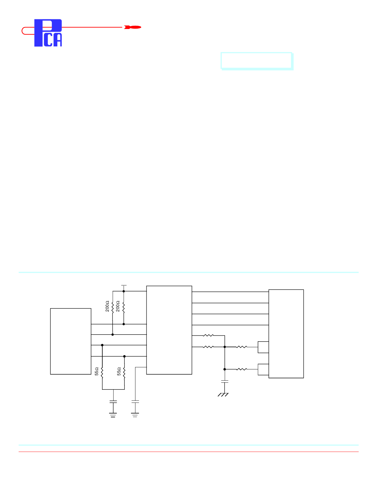
The circuit below is a guideline for interconnecting PCA’s EPF8047SM with ICS 1890 chip for 10/100 Mb/s applications.
Further details can be obtained from the chip manufacturer application notes. Connection to the alternative chip
SSI 78Q2120 is straight forward; please consult the SSI data sheet recommendations for completing this project.
Typical insertion loss of the isolation transformer is 0.5dB. This parameter covers the entire spectrum of the encoded
signals in 10/100 protocols. Under terminated conditions, to transmit a 2V pk-pk signal across the cable, you must adjust
the chips supporting resistor to get at least 2.12V pk-pk across the transmit pins.
Primary side center taps can be returned to the chip side ground plane; but more often than not, if the ground plane is itself
noisy, field experience has shown that it may worsen EMI situation. It is perhaps wiser to carefully lay the system borad
so that substantial gain in EMI suppression is obtained from the so called “common mode termination” on the cable side as
shown below. In any event, this configuration has been known to be quite successful in the field in EMI containment for
similar applications.
The phantom resistors shown around the connector have been known to suppress unwanted radiation that unused wires
pick up from the immediate environment. Their placement and use are to be considered carefully before a design is
finalized.
It is recommended that there be a neat separation of ground planes in the layout. It is generally accepted practice to limit
the plane off at least 0.05 inches away from the chip side pins of EPF8047SM. There need not be any ground plane beyond
this plane.
For best results, PCB designer should design the outgoing traces preferably to be 50 Ω, balanced and well coupled to
achieve minimum radiation from these traces.
Typical Application Circuit for UTP (only one port shown)
5Vcc
TX+
TX-
ICS
1890 RX+
RX-
CM Capacitor
3
35
33
39
2
37
4
34
6
38
8
7
EPF8047SM
1
Rcv
2
75Ω
50Ω
3
Xmit
6
RJ45*
4
5
50Ω
7
8
High Voltage
Capacitor
Chassis
Ground
PCA ELECTRONICS, INC.
16799 SCHOENBORN ST.
NORTH HILLS, CA 91343
Notes : Only one port shown for Hub side connection.
CSF8047SMb Rev. - 8/12/97
TEL: (818) 892-0761
FAX: (818) 894-5791
http://www.pca.com
Share Link: