1883IS Просмотр технического описания (PDF) - Intersil
Номер в каталоге
Компоненты Описание
производитель
1883IS Datasheet PDF : 9 Pages
| |||
EL1883
Applications Information
Video In
A simplified block diagram is shown following page.
An AC coupled video signal is input to Video In pin 2 via C1,
nominally 0.1µF. Clamp charge current will prevent the
signal on pin 2 from going any more negative than Sync Tip
Ref, about 1.5V. This charge current is nominally about 1mA.
A clamp discharge current of about 10µA is always
attempting to discharge C1 to Sync Tip Ref, thus charge is
lost between sync pulses that must be replaced during sync
pulses. The droop voltage that will occur can be calculated
from IT = CV, where V is the droop voltage, I is the discharge
current, T is the time between sync pulses (sync period -
sync tip width), and C is C1.
An NTSC video signal has a horizontal frequency of
15.73kHz, and a sync tip width of 4.7µs. This gives a period
of 63.6µs and a time T = 58.9µs. The droop voltage will then
be V = 5.9mV. This is less than 2% of a nominal sync tip
amplitude of 286mV. The charge represented by this droop
is replaced in a time given by T = CV/I, where I = clamp
charge current = 1mA. Here T = 590ns, about 12% of the
sync pulse width of 4.7µs. It is important to choose C1 large
enough so that the droop voltage does not approach the
switching threshold of the internal comparator.
Composite Sync
The Composite Sync output is simply a reproduction of the
input signal with the active video removed. The sync tip of
the Composite video signal is clamped to 1.5V at pin 2 and
then slices at 70mV above the sync tip reference. The output
signal is buffered out to pin 1. With loss of the input signal,
the Composite Sync output is held low.
Burst
A low-going burst pulse follows each rising edge of sync,
and lasts approximately 3.5µs for an RSET of 681kΩ. With
loss of the input signal, the Back Porch output is held high.
Vertical Sync
A low-going Vertical Sync pulse is output during the start of
the vertical cycle of the incoming video signal. The vertical
cycle starts with a pre-equalizing phase of pulses with a duty
cycle of about 93%, followed by a vertical serration phase
that has a duty cycle of about 15%. Vertical Sync is clocked
out of the EL1883 on the first rising edge during the vertical
serration phase. In the absence of vertical serration pulses,
a vertical sync pulse will be forced out after the vertical sync
default delay time, approximately 60µS after the last falling
edge of the vertical equalizing phase for RSET = 681kΩ. With
loss of the input signal, the vertical output is held low.
Horizontal Sync
The Horizontal circuit senses the composite sync edges and
produces the true horizontal pulses of nominal width 5.2µs
with RSET = 681kΩ. The leading edge is triggered from the
leading edge of the input H sync, with the same propagation
delay as composite sync. The half line pulses present in the
input signal during vertical blanking are removed with an
internal 2H line eliminator circuit. This is a circuit that inhibits
horizontal output pulses until 75% of the line time is reached,
then the horizontal output operation is enabled again. Any
signals present on the I/P signal after the true H sync will be
ignored, thus the horizontal output will not be affected by
MacroVision copy protection. With loss of the input signal,
the Horizontal Sync output is held high.
RSET
An external RSET resistor, connected from RSET pin 6 to
ground, produces a reference current that is used internally
as the timing reference for vertical sync width, vertical sync
default delay, burst gate delay and burst width. Decreasing
the value of RSET increases the reference current, which in
turn decreases reference times and pulse widths. A higher
frequency video input necessitates a lower RSET value.
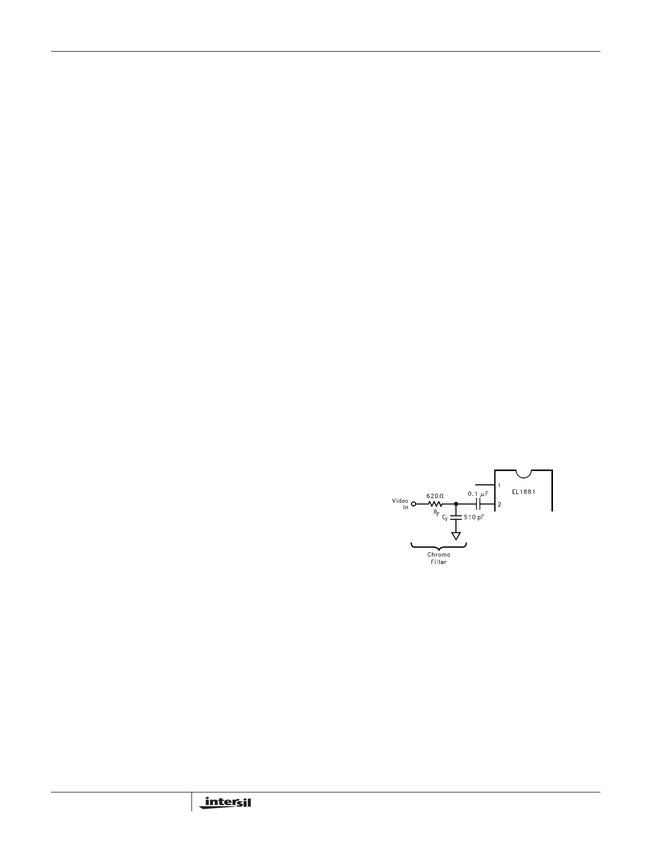
Chroma Filter
A chroma filter is suggested to increase the S/N ratio of the
incoming video signal. Use of the optional chroma filter is
shown in the figure below. It can be implemented very simply
and inexpensively with a series resistor of 620Ω and a
parallel capacitor of 500pF, which gives a single pole roll-off
frequency of about 500kHz. This sufficiently attenuates the
3.58MHz (NTSC) or 4.43MHz (PAL) color burst signal, yet
passes the approximately 15kHz sync signals without
appreciable attenuation. A chroma filter will increase the
propagation delay from the composite input to the outputs.
8
Share Link: 