EK17 Просмотр технического описания (PDF) - Apex Microtechnology
Номер в каталоге
Компоненты Описание
производитель
EK17 Datasheet PDF : 4 Pages
| |||
EK17
EVALUATION KIT
FOR SA12 PWM AMPLIFIER
ASSEMBLY
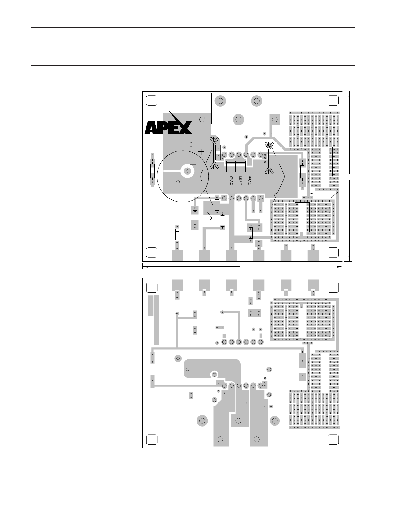
FIGURE 2. PCB
During assembly refer to Figures 1 & 2 ��������
1. From the DUT of the PCB insert and
���
solder the 12 cage jacks. Also solder
the cage jacks from the circuit side
as well, making sure the cage jack
remains flush with the component side
of the PCB.
2. Solder the 3 surface mount ceramic
capacitors to the component side of
the PCB.
��� ����� ���
���
� � � ��� �� ���� ���
����������
��������������
� ��
�
����� ���
��
3. From the component side of the PCB
insert the terminal strip. Solder from the
�
��
��
circuit side of the PCB. Be sure that ��
the GND terminal hole in the PCB is
��
�����
fully filled with solder.
����
4. Two values of current limiting power
resistors are supplied. Select one
��� ���
���
value (see the amplifier data sheet to
learn how to calculate which resistor
�
�
��
will suit your need). Coat the backside
of the power resistor with heat sink
��
��� ��
��
��
���
compound (not supplied). Using 4-40
screws and nuts (not supplied) mount
the resistors to the two small heat sinks
supplied. Solder the resistor/heat sink
����
��
���������
��
����
���
���
��
��
����
�����
�����
assembly to the component side of the
PCB.
�����
5. Insert the electrolytic capacitor into
�����������
the PCB from the component side and
solder from the circuit side making sure
to fill the mounting holes with solder.
6. From the circuit side, push spacer
grommets into PCB until fully seated.
Grommets will snug when screws are
inserted for heatsink mounting.
7. Apply TW05 thermal washer to the
bottom of the amplifier.
8. Use #14 sleeving to insulate and align
at least 2 opposite pins of the ampli-
fier.
9. Mount amplifier to heatsink using #6
screws and nuts. Torque the part to
the specified 8 to 10 in-lbs (.9 to 1.13
N*M). Do not over torque.
10. Install components as needed. Ex-
ternal connections may be soldered
directly or standard banana jacks may
be soldered to the large pads at the
edge of the PCB.
11. Insert amplifier pins into cage jacks
and fasten PCB to heatsink.
APEX MICROTECHNOLOGY CORPORATION • 5980 NORTH SHANNON ROAD • TUCSON, ARIZONA 85741 • USA • APPLICATIONS HOTLINE: 1 (800) 546-2739
2
Share Link: 