DR-7401 Просмотр технического описания (PDF) - Unspecified
Номер в каталоге
Компоненты Описание
производитель
DR-7401 Datasheet PDF : 1 Pages
| |||
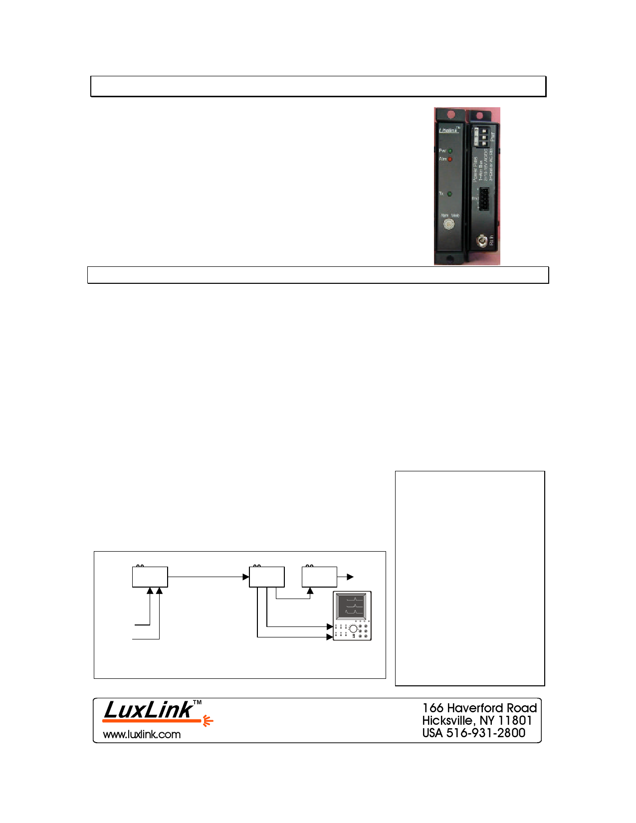
Data & Clock Transmission
For Medium Speed Data & Clock Applications
The Litelink™ DX-7401/DT-7401/DR-7401 system consists of
the DX-7401 transceiver, DT-7401 dual channel transmitter and
DR-7402 dual channel receiver. All units are designed to
transmit clock and companion data signals on a single fiber (per
channel) by utilizing Manchester encoding and decoding of the
signals. Standard digital modulation is then used to transmit the
composite signal, error free, through the fiber optic cable.
The DX-7401/DT-740`/DR-7401 are all adjustment free and
integral LEDs are provided on all units to continuously indicate
the presence of operating power and transmitter/receiver
synchronization thereby making system troubleshooting simple.
Technical Specifications
DX/DT/DR-7401
Important Features
Overall Bandwidth (minimum)
Clock Input / Output
Data Input / Output
Input / Output Levels
Input / Output Termination
Operating Wavelength
Optical Output Power
Optical Loss Budget
Optical Connectors
Indicator LEDs
Signal Connector
Operating Temperature
Power Requirements**
Physical Size (mm)
DC to 20 Mb/s
10 MHz
DC to 10 Mb/s
Standard TTL
330/220 ohms pull up/down
850, 1310 or 1550nm
-16dBm (multimode)
-16dBm (single-mode)
0-10dB (multimode)
0-10dB (single-mode)
ST (multimode)
FCPC (single-mode)
Power, Link, Alarm
DB-37 Female
-35° to +75°C
11-18 VAC/DC @150ma.
5.0” (127) x 3.0” (76)
x 1.0” (25.4)
• 10 MHz Clock Rate
10 Mb/s Data Rate
• Signal/Power Indicators
• Multimode or Single-
mode versions
• Stand-alone or Rack
Mountable (same unit)
Ordering Information
Transceiver DX-7401-X
Transmitter DT-7401-X
Receiver DR-7401-X
Note that all specifications are subject to change without prior notice.
DT-7401
Single Fiber
Optic Cable
DR-7401
ALM-1000
Alarm
Contacts
“X” = Wavelength/Fiber
-1 = 850nm Multimode
-3 = 1310nm Multimode
-7 = 1310nm Single-mode
-9 = 1550nm Single-mode
Data
Signal
Data
Source
Clock
Clock
Signal
Measurement
Typical Data & Clock Application
For stand-alone operation order a
PS-1205 power supply for each
unit.
For rack mounted operation all
operating power is provided by
power supply used with the rack-
mounting panel.
Share Link: 