SPX2730 Просмотр технического описания (PDF) - Signal Processing Technologies
Номер в каталоге
Компоненты Описание
производитель
SPX2730
Signal Processing Technologies

SPX2730 Datasheet PDF : 9 Pages
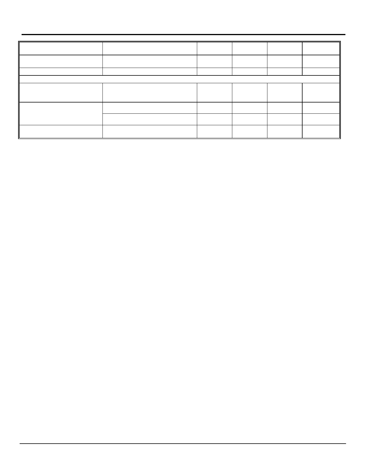
| |||
(Cont.)
Upper Threshold
Voltage
Lower Threshold
Voltage
Hysteresis
Device set for 5V (Note 9)
Device set for 5V (Note 9)
Device set for 5V (Note 9)
ENABLE Input SPX2731/SPX2732
Input Logic Voltage
Low (OFF)
High (ON)
Enable Pin
Input Current
VEN = 16V
VEN = 0.8V
Regulator Output
Current in Shutdown
(Note 10)
SPX2730/31/32/33
60
40
mV
25
75
95
mV
140
15
mV
0.8
V
2.4
100
600
V
750
1
µA
2
10
µA
500
Notes:
The Bold specifications apply to the full operating temperature range.
Note 1: Maximum positive supply voltage of 60V must be of limited duration (<100msec) and duty cycle.) The maximum continuous supply voltage is 16V.
Note 2: Full load current (IFL) is defined as 1.5A for the
Note 3: Dropout voltage is defined as the input-to output differential when the output voltage drops to 99% of its nominal value with VOUT + 1V applied to VIN.
Note 4: VIN = VOUT (NOMINAL) +1V. For example, use VIN= 4.3V for a3.3V regulator. Employ pulse-testing procedures to minimize temperature rise.
Note 5: Ground pin current is the regulator quiescent current. The total current drawn from the source is the sum of the load current to the ground current.
Note 6: Output voltage temperature coefficient is defined as the worst case voltage changed divided by the total temperature range.
Note 7: Thermal regulation is defined as the change in the output voltage at a time T after a change in power dissipation is applied, excluding load or line regulation
effects. Specifications are for a 200mA load pulse as VIN = 20V (a 4W pulse) for T = 10ms.
Note 8: VREF ≤ VOUT ≤ (VIN – 1), 2.3V ≤ VIN≤ 16V, 10mA < IL ≤ IFL, TJ ≤ TJMAX
Note 9: Comparator threshold is expressed in terms of a voltage differential at the Adjust terminal below the nominal reference voltage measured a 6V input. To
express these thresholds in terms of output voltage change, multiply the error amplifier gain = VOUT/VREF = (R1 + R2)R2. For example, at a programmable output
voltage of 5V, the Error output is guaranteed to go low when the output drops by 95mVx 5V/ 1.240V = 38mV. Threshold remain constant as a percent of VOUT as VOUT
is varied, with the dropout warning occurring at typically 5% below nominal, 7.7% guaranteed.
Note 10: VEN ≤ 0.8V and VIN ≤ 16V, VOUT = 0.
Rev. 12/7/00
Share Link: