DS2465 Просмотр технического описания (PDF) - Maxim Integrated
Номер в каталоге
Компоненты Описание
производитель
DS2465 Datasheet PDF : 31 Pages
| |||
ABRIDGED DATA SHEET
DS2465
SHA-256 Coprocessor with 1-Wire Master Function
VCC
VIAPO
0V
LAST BIT OF 1-Wire WRITE BYTE, 1-Wire READ BYTE, OR 1-Wire SINGLE BIT FUNCTION
WRITE-ONE CASE
WRITE-ZERO CASE
tSLOT
DS2465 RESISTIVE PULLUP
DS2465 PULLDOWN
NEXT
TIME SLOT
DS2465 STRONG PULLUP
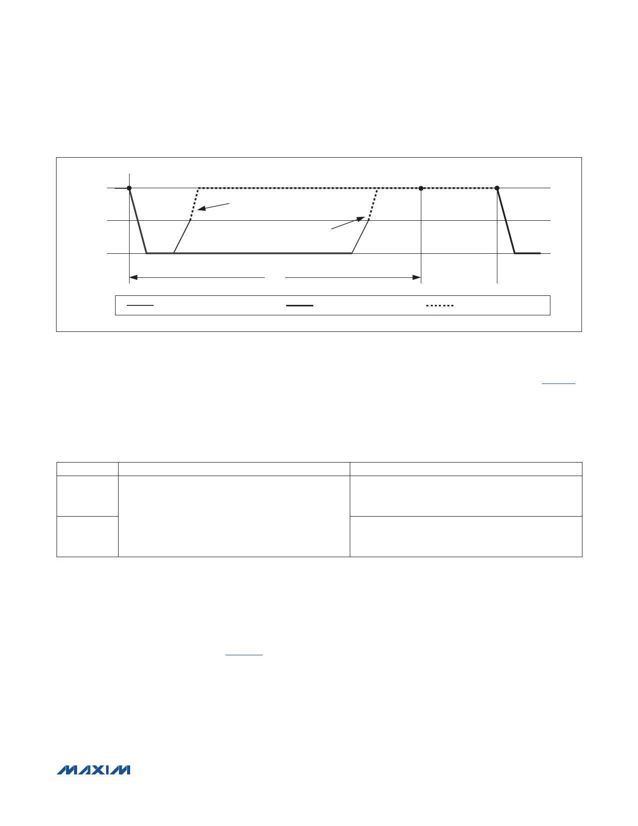
Figure 3. Low-Impedance Pullup Timing
Bit 1: 1-Wire Power-Down (PDN). The PDN bit is used to remove power from the 1-Wire port, e.g., to force a 1-Wire
slave to perform a power-on reset. PDN interacts with the sleep mode, which is controlled by the SLPZ pin (Table 4).
The default state of PDN is 0, enabling normal operation. When PDN is changed to 1, no 1-Wire communication is
possible. To end the 1-Wire power-down state, the PDN bit needs to be changed to 0. To exit the DS2465 from sleep
mode, change the SLPZ pin state from 0 to 1. This forces the DS2465 to perform a power-on reset and clears PDN to
0 for normal operation.
Table 4. Interaction of PDN and SLPZ
SLPZ PIN IS AT LOGIC 0
PDN is 0
PDN is 1
• RWPU is disconnected;
IO is at 0V, causing the slaves to lose power.
• The DS2465 is powered down (sleep mode).
SLPZ PIN IS AT LOGIC 1
• RWPU is connected;
IO is at VCC, keeping the slaves powered.
• The DS2465 is powered up (normal operation).
• RWPU is disconnected;
IO is at 0V, causing the slaves to lose power.
• The DS2465 is powered up.
Bit 0: Active Pullup (APU). The APU bit controls whether an active pullup (low impedance transistor) or a passive
pullup (RWPU resistor) is used to drive a 1-Wire line from low to high. When APU = 0, active pullup is disabled (resistor
mode). Enabling active pullup is generally recommended for best 1-Wire performance. The active pullup does not apply
to the rising edge of a recovery after a short on the 1-Wire line. If enabled, a fixed-duration active pullup (nominally
2.5Fs standard speed, 0.5Fs overdrive speed) also applies in a reset/presence detect cycle on the rising edges after
tRSTL and after tPDL.
The circuit that controls rising edges (Figure 4) operates as follows: At t1, the pulldown (from DS2465 or 1-Wire slave)
ends. From this point on the 1-Wire line is pulled high through RWPU internal to the DS2465. VCC and the capacitive load
of the 1-Wire line determine the slope. In case that active pullup is disabled (APU = 0), the resistive pullup continues,
as represented by the solid line. With active pullup enabled (APU = 1), and when at t2 the voltage has reached the
VIAPO threshold, the DS2465 activates a low-impedance pullup transistor, as represented by the dashed line. The active
pullup remains active until the end of the time slot (t3), after which the resistive pullup continues. The shortest duration
of the active pullup is tREC0 in a write-zero time slot and the longest duration is tW0L + tREC0 - tW1L in a write-one time
slot. In a read data time slot, the active pullup duration is slave dependent. See the strong pullup (SPU) section for a
way to keep the pullup transistor conducting beyond t3.
���������������������������������������������������������������� Maxim Integrated Products 11
Share Link: 