DS2155DK Просмотр технического описания (PDF) - Maxim Integrated
Номер в каталоге
Компоненты Описание
производитель
DS2155DK Datasheet PDF : 21 Pages
| |||
DS2155DK/DS2156DK T1/E1/J1 Single-Chip Transceiver Design Kit Daughter Cards
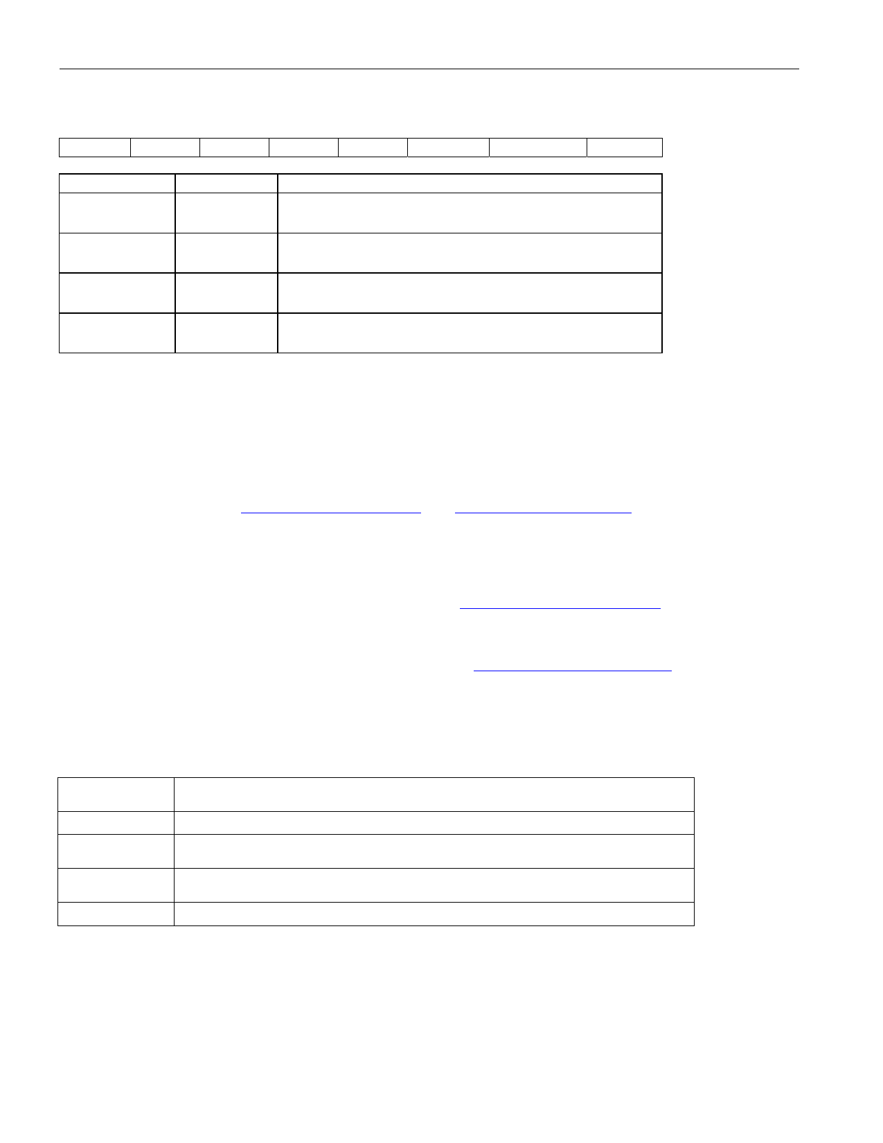
LEVELS: SET LEVEL ON PIN (Offset = 0X0015) INITIAL VALUE = 0x6
(MSB)
(LSB)
—
—
—
—
—
BP_EN PPCTDM_EN TUSEL
NAME
—
BP_EN
PPCTDM_EN
TUSEL
POSITION
FUNCTION
LEVELS1.3 —
LEVELS1.2
LEVELS1.1
LEVELS1.0
0 = Enable IDT switches that connect the UTOPIA bus to
daughter card header
0 = Enable IDT switches that connect the TDM bus to the
daughter card header
0 = Set DS2156.TUSEL to enable TDM backplane
1 = Set DS2156.TUSEL to enable UTOPIA backplane
Note: When the UTOPIA backplane is enabled (LEVELS.TUSEL = 1) there is a possibility for contention between
the UTOPIA bus master and TSYSCLK, TSER, and RSER. To avoid this, the following switches should be opened
when the UTOPIA backplane is enabled: SWITCH1.0, SWITCH2.0, SWITCH3.0, and SWITCH4.1
DS2155/DS2156 INFORMATION
For more information about the DS2155 and DS2156, please consult the DS2155 and DS2156 data sheets
available on our website at www.maxim-ic.com/DS2155 and www.maxim-ic.comDS2156. Software downloads are
also available for this design kit.
DS2155DK/DS2156DK INFORMATION
For more information about the DS2155DK and DS2156DK, including software downloads, please consult the
DS2155DK/DS2156DK data sheet available on our website at www.maxim-ic.com/DS2155DK.
TECHNICAL SUPPORT
For additional technical support, please e-mail your questions to telecom.support@dalsemi.com.
SCHEMATICS
The DS2155DK/DS2156DK schematics are featured in the following 13 pages.
DOCUMENT REVISION HISTORY
REVISION
DATE
DESCRIPTION
032503
Initial DS2155DK/DS2156DK data sheet release.
060303
012705
Updated the Title, General Description, Features, and Basic Operation
sections; “TIM” replaced with “daughter card.”
Updated schematics (removed component values for Fuse and Sidactor; see
Component List).
110106
Updated schematics.
8 of 21
Maxim/Dallas Semiconductor cannot assume responsibility for use of any circuitry other than circuitry entirely embodied in a Maxim/Dallas Semiconductor product.
No circuit patent licenses are implied. Maxim/Dallas Semiconductor reserves the right to change the circuitry and specifications without notice at any time.
Maxim Integrated Products, 120 San Gabriel Drive, Sunnyvale, CA 94086 408-737-7600
© 2006 Maxim Integrated Products
The Maxim logo is a registered trademark of Maxim Integrated Products, Inc. The Dallas logo is a registered trademark of Dallas Semiconductor.
Share Link: 