RMPA39200(2001) Просмотр технического описания (PDF) - Raytheon Company
Номер в каталоге
Компоненты Описание
производитель
RMPA39200 Datasheet PDF : 7 Pages
| |||
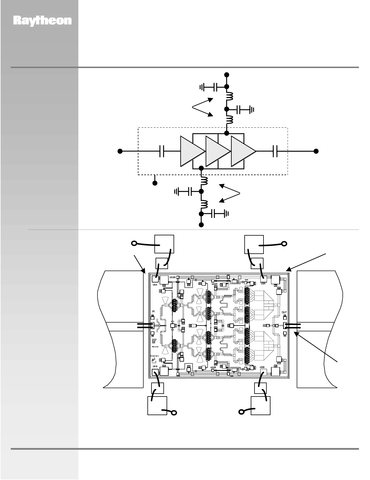
Figure 3
Recommended
Application Schematic
Circuit Diagram
RMPA39200
37-40 GHz 1.6 Watt Power
Amplifier MMIC
ADVANCED INFORMATION
Drain Supply (Vd= +5V)
10,000 pF (Connect to both VDA & VDB)
Bond Wire L’s
L
100 pF
L
MMIC Chip
RF IN
RF OUT
Figure 4
Recommended
Assembly and
Bonding Diagram
Ground
100 pF
L
(Back of Chip)
L
Bond Wire L’s
Gate Supply (Vg)
(VGA and/or VGB)
10,000 pF
Vg
(Negative)
2 mil Gap
10,000 pF
100 pF
10,000 pF
100 pF
Vd
(Positive)
Die-Attach
80Au/20Sn
5mil Thick
Alumina
50-Ohm
RF
Input
5 mil Thick
Alumina
50-Ohm
RF
Output
L< 0.015”
(4 Plcs)
www.raytheon.com/micro
100 pF
100 pF
10,000 pF
Vg
(Negative)
Vd
(Positive)
10,000 pF
Note:
Use 0.003” x 0.0005” Gold Ribbon for bonding. RF input and output bonds should be less than 0.015” long with stress relief. Vd should be
biased from 1 supply on both sides as shown.Vg can be biased from either or both sides from 1 supply.
Characteristic performance data and specifications are subject to change without notice.
Revised July 27, 2001
Page 3
Raytheon RF Components
362 Lowell Street
Andover, MA 01810
Share Link: 