CY3683 Просмотр технического описания (PDF) - Cypress Semiconductor
Номер в каталоге
Компоненты Описание
производитель
CY3683 Datasheet PDF : 15 Pages
| |||
CY7C68000A
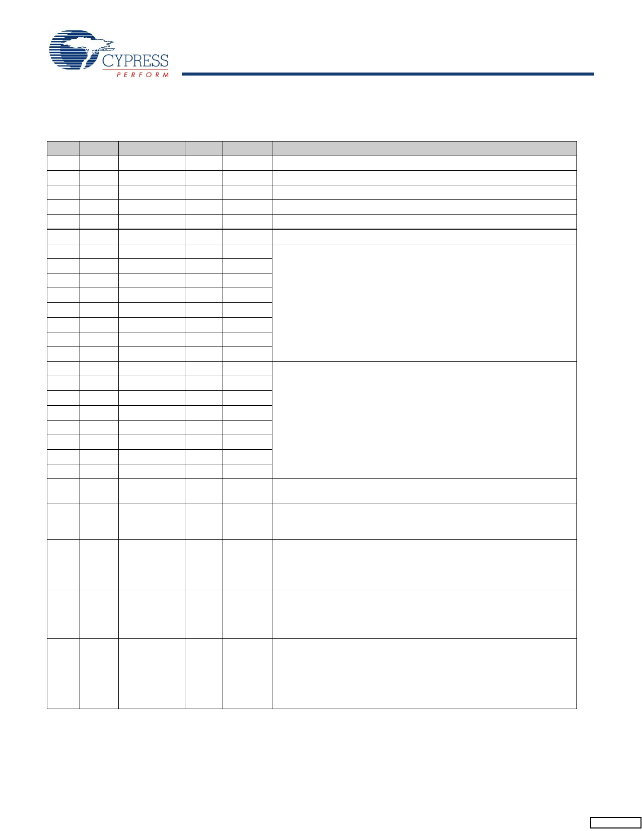
Pin Descriptions
Table 1. Pin Descriptions
QFN
4
8
7
11
9
10
49
48
46
44
43
41
39
38
37
36
34
33
31
29
27
26
50
VFBGA Name
H1 AVCC
H5 AVCC
H4 AGND
H8 AGND
H6 DPLUS
H7 DMINUS
G8 D0
G7 D1
G5 D2
G3 D3
G2 D4
F8 D5
F6 D6
F5 D7
F4 D8
F3 D9
F1 D10
G4 D11
E1 D12
D8 D13
G1 D14
E2 D15
A1 CLK
3
B2 Reset
12
B3 XcvrSelect
13
B4 TermSelect
2
B1 Suspend
Type
Power
Power
Power
Power
I/OZ
I/OZ
I/O
I/O
I/O
I/O
I/O
I/O
I/O
I/O
I/O
I/O
I/O
I/O
I/O
I/O
I/O
I/O
Output
Input
Input
Input
Input
Default
N/A
N/A
N/A
N/A
Z
Z
Description[1]
Analog VCC This signal provides power to the analog section of the chip.
Analog VCC This signal provides power to the analog section of the chip.
Analog Ground Connect to ground with as short a path as possible.
Analog Ground Connect to ground with as short a path as possible.
USB DPLUS Signal Connect to the USB DPLUS signal.
USB DMINUS Signal Connect to the USB DMINUS signal.
Bidirectional Data Bus This bidirectional bus is used as the entire data
bus in the 8-bit bidirectional mode or the least significant eight bits in the
16-bit mode. Under the 8-bit unidirectional mode, these bits are used as
inputs for data, selected by the RxValid signal.
Bidirectional Data Bus This bidirectional bus is used as the upper eight
bits of the data bus when in the 16-bit mode, and not used when in the
8-bit bidirectional mode. Under the 8-bit unidirectional mode these bits
are used as outputs for data, selected by the TxValid signal.
Clock This output is used for clocking the receive and transmit parallel
data on the D[15:0] bus.
N/A Active HIGH Reset Resets the entire chip. This pin can be tied to VCC
through a 0.1-μF capacitor and to GND through a 100 K resistor for a
10-ms RC time constant.
N/A Transceiver Select This signal selects between the Full Speed (FS) and
the High Speed (HS) transceivers:
0: HS transceiver enabled
1: FS transceiver enabled
N/A Termination Select This signal selects between the Full Speed (FS) and
the High Speed (HS) terminations:
0: HS termination
1: FS termination
N/A Suspend Places the CY7C68000A in a mode that draws minimal power
from supplies. Shuts down all blocks not necessary for Suspend/Resume
operations. While suspended, TermSelect must always be in FS mode
to ensure that the 1.5 Kohm pull up on DPLUS remains powered.
0: CY7C68000A circuitry drawing suspend current
1: CY7C68000A circuitry drawing normal current
Note
1. Unused inputs should not be left floating. Tie either HIGH or LOW as appropriate. Outputs that are three-statable should only be pulled up or down to ensure
signals at power-up and in standby.
Document #: 38-08052 Rev. *H
Page 6 of 15
[+] Feedback
Share Link: 