CUS04 Просмотр технического описания (PDF) - Toshiba
Номер в каталоге
Компоненты Описание
производитель
CUS04 Datasheet PDF : 5 Pages
| |||
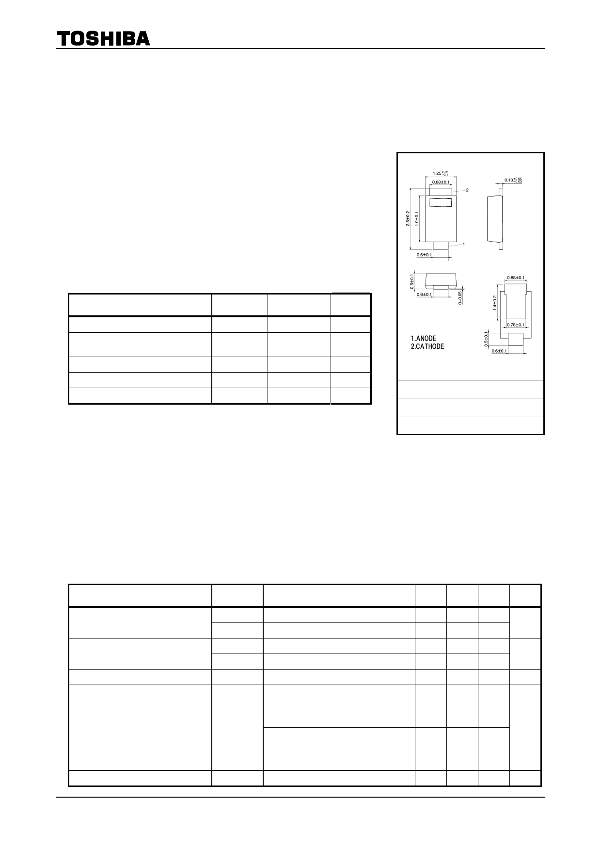
TOSHIBA Schottky Barrier Rectifier Schottky Barrier Type
CUS04
Switching Mode Power Supply Applications
Portable Equipment Battery Application
CUS04
Unit: mm
• Forward voltage: VFM = 0.58 V@IF = 0.7 A
• Average forward current: IF (AV) = 0.7A
• Repetitive peak reverse voltage: VRRM = 60 V
• Suitable for compact assembly due to small surface-mount package
“US−FLATTM” (Toshiba package name)
Absolute Maximum Ratings (Ta = 25°C)
Characteristics
Symbol
Rating
Unit
Repetitive peak reverse voltage
Average forward current
VRRM
IF (AV)
60
V
0.7
(Note 1)
A
Peak one cycle surge forward current
IFSM
20 (50 Hz)
A
Junction temperature
Storage temperature range
Tj
−40 to 150
°C
Tstg
−40 to 150
°C
Note 1: Ta = 27°C:
Device mounted on a glass-epoxy board
Board size: 50 mm × 50 mm,
Land size: 6 mm × 6 mm
Rectangular waveform (α = 180°), VR = 30 V
JEDEC
―
JEITA
TOSHIBA
3-2B1A
Weight: 0.004 g (typ.)
Note 2:
Using continuously under heavy loads (e.g. the application of high temperature/current/voltage and the
significant change in temperature, etc.) may cause this product to decrease in the reliability significantly
even if the operating conditions (i.e. operating temperature/current/voltage, etc.) are within the absolute
maximum ratings.
Please design the appropriate reliability upon reviewing the Toshiba Semiconductor Reliability Handbook
(“Handling Precautions”/Derating Concept and Methods) and individual reliability data (i.e. reliability test
report and estimated failure rate, etc).
Electrical Characteristics (Ta = 25°C)
Characteristics
Peak forward voltage
Repetitive peak reverse current
Junction capacitance
Thermal resistance
(junction to ambient)
Thermal resistance (junction to lead)
Symbol
Test Condition
Min
VFM (1) IFM = 0.1 A
―
VFM (2) IFM = 0.7 A
―
IRRM (1) VRRM = 5 V
―
IRRM (2) VRRM = 60 V
―
Cj
VR = 10 V, f = 1.0 MHz
―
Device mounted on a ceramic board
(board size: 50 mm × 50 mm)
(soldering land: 2 mm × 2 mm)
―
Rth (j-a)
(board thickness: 0.64 t)
Device mounted on a glass-epoxy board
(board size: 50 mm × 50 mm)
(soldering land: 6 mm × 6 mm)
―
(board thickness: 1.6 t)
Rth (j-ℓ) Junction to lead of cathode side
―
Typ.
0.40
0.55
0.3
3.0
38
―
―
―
Max Unit
―
V
0.58
―
μA
100
―
pF
75
°C/W
150
30 °C/W
1
2006-11-13
Share Link: 