CRG04 Просмотр технического описания (PDF) - Toshiba
Номер в каталоге
Компоненты Описание
производитель
CRG04 Datasheet PDF : 4 Pages
| |||
TOSHIBA Rectifier Silicon Diffused Type
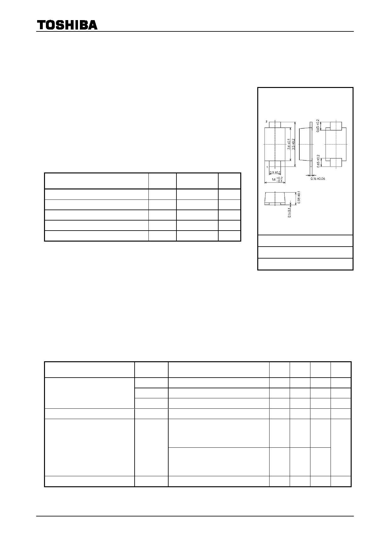
CRG04
○ General Power Supply Rectification
• Repetitive peak reverse voltage : VRRM = 600 V
• Average forward current
: IF (AV) = 1.0 A
• Peak forward voltage
: VFM = 1.1 V (max)
• The use of small, thin surface-mount package is optimum way
for high-density mounting.
Nickname: S-FLATTM
CRG04
Unit: mm
Absolute Maximum Ratings (Ta = 25°C)
Characteristics
Symbol
Rating
Unit
Repetitive Peak Reverse Voltage
VRRM
600
V
Average Forward Current
IF (AV)
1.0 (Note1)
A
Non-repetitive peak forward surge current
IFSM
15 (50Hz)
A
Junction Temperature
Tj
−40 to 150
°C
Storage Temperature Range
Tstg
−40 to 150
°C
Note 1: Ta = 66°C Device mounted on a ceramic board
board size
:50 mm × 50 mm
Soldering land size :2 mm × 2 mm
board thickness
:0.64 mm
Half-sine waveform :α = 180°
1 ANODE
2 CATHODE
JEDEC
―
JEITA
―
TOSHIBA
3-2A1S
Weight: 0.013 g (typ.)
Note:
Using continuously under heavy loads (e.g. the application of
high temperature/current/voltage and the significant change in temperature, etc.) may cause this product to
decrease in the reliability significantly even if the operating conditions (i.e. operating
temperature/current/voltage, etc.) are within the absolute maximum ratings.
Please design the appropriate reliability upon reviewing the Toshiba Semiconductor Reliability Handbook
(“Handling Precautions”/“Derating Concept and Methods”) and individual reliability data (i.e. reliability test
report and estimated failure rate, etc).
Electrical Characteristics (Ta = 25°C)
Characteristics
Symbol
Test Condition
Min Typ. Max Unit
VFM(1) IFM = 0.1 A (Pulse test)
― 0.84 ―
V
Peak forward voltage
VFM(2) IFM = 0.7 A (Pulse test)
― 0.95 ―
V
VFM(3) IFM = 1.0 A (Pulse test)
― 0.98 1.1
V
Repetitive peak reverse current
IRRM VRRM = 600 V (Pulse test)
―
―
10
μA
Thermal resistance
(junction to ambient)
Device mounted on a ceramic board
board size
50 mm × 50 mm
soldering land size 2 mm × 2 mm
―
Rth (j-a)
board thickness
0.64 mm
Device mounted on a glass-epoxy board
board size
50 mm × 50 mm
soldering land size 6 mm × 6 mm
―
board thickness
1.6 mm
―
65
°C/W
―
130
Thermal resistance (junction to lead) Rth (j-ℓ)
―
―
―
20 °C/W
Start of commercial production
2004-08
1
2019-04-22
Share Link: 