CMX869E2 Просмотр технического описания (PDF) - CML Microsystems Plc
Номер в каталоге
Компоненты Описание
производитель
CMX869E2 Datasheet PDF : 46 Pages
| |||
Low Power V.32 bis Modem
CMX869
In the receive direction, the signal detection thresholds within the CMX869 are proportional to AVDD and
are affected by the Rx Gain Control gain setting in the Rx Mode Register. The signal level into the
CMX869 is affected by the line coupling transformer loss and the values of R11 and R12 of Figure 4a.
The value of R11 should be chosen so that the received signal level at the RXAFB pin is 3.6dB lower
than that on the 2-wire line. For example if the transformer loss is 1dB then R11 should be 130kΩ. The
value of R14 (15kΩ) is chosen to apply approximately 20dB of extra gain, when required by Type 1
Caller Line Identification.
For best Rx performance, it is recommended that the transformer coupling arrangement should provide
at least 7dB trans-hybrid loss.
The RXBN input can be selected by setting bit 14 of the General Control Register to 1, which internally
connects RXBN to RXAN. With the components shown in Figures 4a and 4b, this will add approximately
20dB to the Rx gain, by connecting R14 in parallel with R11. This facilitates detection of certain signals
whilst on-hook, such as may be required for Type 1 Caller Line Identification reception. For the 2-wire line
interface shown in Figure 4a, capacitor C12 is required to provide an AC path through to the device when
the relay is open. If this facility is not required, R14 and C12 can be omitted.
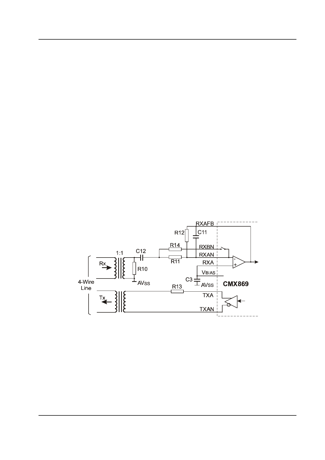
4-Wire Line Interface
Figure 4b shows a simplified interface for use with a 600Ω 4-wire line. The line terminations are provided
by R10 and R13, high frequency noise is attenuated by C11 while R11 and R12 set the receive signal
level into the modem. Transmit and receive line level settings and the values of R11 and R14 are as for
the 2-wire circuit.
R10, 13
R11
R12
R14
600Ω
C3
130kΩ (see text)
C11
100kΩ
C12
15kΩ (see text)
Resistors ±5%, capacitors ±20%
See Figure 2
100pF
33nF
Figure 4b 4-Wire Line Interface Circuit
© 2003 CML Microsystems Plc
10
D/869/1
Share Link: 