CMX838 Просмотр технического описания (PDF) - CML Microsystems Plc
Номер в каталоге
Компоненты Описание
производитель
CMX838 Datasheet PDF : 71 Pages
| |||
FRS/PMR446/GMRS Family Radio Processor
CMX838
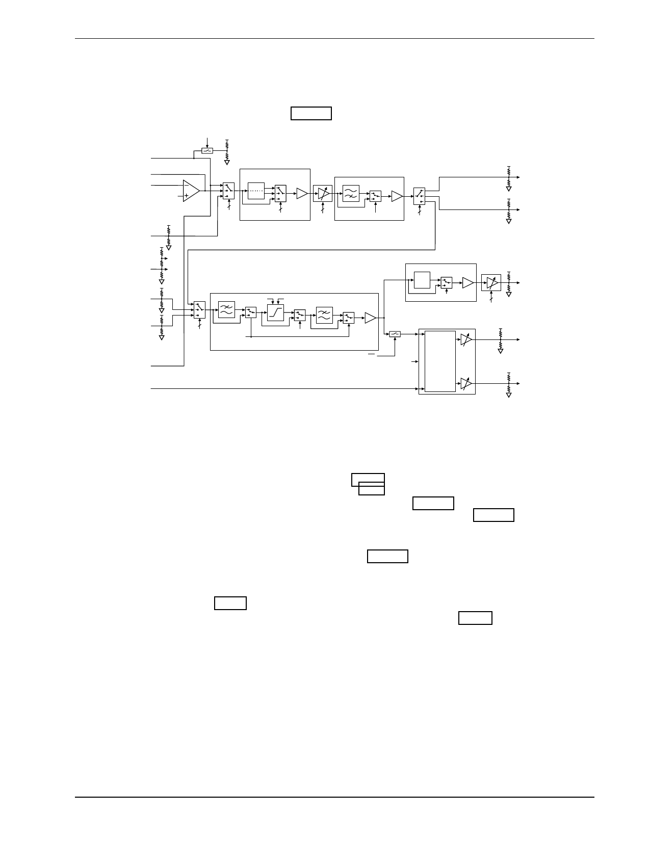
4 General Description
4.1 Audio
The audio signal processing is designed to meet or exceed the requirements for basic audio filtering, gain
control and deviation limiting in a FRS radio. Figure 3 is a block diagram of the audio circuitry.
AUXPUPEN
AUX I/O
MICOUT
MICIN
VREF
RXIN
PREEMPHASIS OR 2ND
ORDER LPF
LP
PRE
1
AUDIO
INPUT 1
SELECT
PRE LPF CTRL
AUDIO
LEVEL
6TH ORDER HPF
1
HPF BYPASS
AUDIO OUT
SELECT
AOUT
BOUT
VBIAS
TOS
VREF
AIN
VLL
VLH
BIN
AUDIO
INPUT 2 LPF BYPASS
LIMITER BYPASS
SELECT
DEVIATION LIMITER AND POST-LIMITER LPF
TONE GENERATOR
1
TX/RX
TX SUBAUDIO (From On-Chip Subaudio Tone Generator)
DEEMPHASIS NETWORK
DE
1
DEBP
RX AUDIO OUT
LEVEL
RXOUT
TOS
TXMOD
SWITCH
MATRIX and
PHASE
CONTROL
See Figure 4
TXMOD1
TXMOD2
Figure 3: Audio Processing Block Diagram
4.1.1 Digitally Controlled Amplifiers (DCA)
There are five DCAs on-chip. They are used to set signal levels for audio in/out, subaudio in/out, receive
audio out (volume control), modulation out1, and modulation out2. The audio in/out DCA is adjustable in
0.5dB steps over a +7.5dB to –7.5dB range, see Section 5.1.2.3. The volume control level DCA is adjustable
in 1.5dB steps over a +12dB to –33dB range, see Section 5.1.2.4. The subaudio signal level in/out DCA is
adjustable in 0.5dB steps over a +7.5dB to –7.5dB range, see Section 5.1.2.19
The modulation level controls are composed of two DCAs, and a switch matrix, see Figure 4. Each
modulation level DCA, modulation out1 and modulation out2, can be switched to select either the output of
the audio processor, or the output of the tone generator, or the addition of the audio and tone. In addition,
there is an internally generated DC volume (labeled ‘TOS’ in Figure 4), which can be sent to the MOD1 and
MOD2 DCA’s. This signal is not generally applicable to FRS radios. However, in some cases it may be
desirable for testing or signal generation. The modulation out1 DCA is adjustable in 0.5dB steps over a
+7.5dB to –7.5dB range and the Modulation Out2 DCA is adjustable in 0.25dB steps over a +3.75dB to
-3.75dB range, see Section 5.1.2.6. To obtain inverse signals of mod 1and mod 2, the MSB from the first byte
(bit 7) and the MSB from second byte (bit 15) have to set to logic 1, see Section 5.1.2.6.
2003 CML Microsystems Plc
10
D/838/8
Share Link: 