PBL40309 Просмотр технического описания (PDF) - Ericsson
Номер в каталоге
Компоненты Описание
производитель
PBL40309 Datasheet PDF : 6 Pages
| |||
PBL 403 09
DECT RADIO WITH PBL402 15 TRANSCEIVER
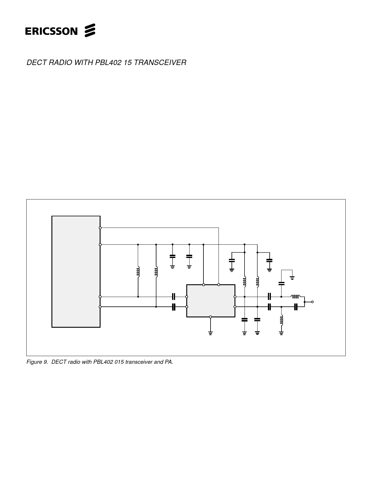
PBL403 09 together with the transceiver chip PBL402 15 form the base of the radio platform for DECT systems. The transmission
part of the chip PBL402 15 has a differential output which can deliver up to 7 dBm. The output power can be programmed in steps.
The outputs are of open-collector type. Suitable network between PBL402 15 and PBL403 09 is therefore shunt inductors from the
open-collectors to Vcc and series capacitors to the RF inputs of PBL403 09. Suitable value of the capacitors is 1 to 5 pF in order to
compensate for the series inductance of the PCB and package. Input impedance of the PBL403 09 is 50 Ω differential.
The ideal collector load of the open collector RF output of PBL403 09 is about 11 Ω per side. A matching and combination network to
50 Ω single ended case is shown in fig.9. A shunt capacitor (2.7 pF) transforms each output to 50 Ω. Both 50 Ω outputs are AC coupled
and then combined with an LC-CL structure to a 50 Ω single ended output.
A power control signal with active low is received from PBL402 15. This signal controls power up/down of the PBL403 09.
Supply decoupling consists of high frequency and low frequency decoupling capacitors. The high frequency decoupling capacitor
should be placed close to the Vcc pin.
PA-ON
25
41 Vcc
PBL 402 15
38 Tx-
Tx+
39
33p 10n
100p
100p
3.9n 3.9n
1.5p
1.5p
8
1
3 PBL 403 09 14
6
11
68 68
nn
33p
33p
2.7p
2.7p
1.1p
5.6n
1.1p
5.6n
GND
output
Figure 9. DECT radio with PBL402 015 transceiver and PA.
5
Share Link: 