PBL40309 Просмотр технического описания (PDF) - Ericsson
Номер в каталоге
Компоненты Описание
производитель
PBL40309 Datasheet PDF : 6 Pages
| |||
PBL 403 09
Application information.
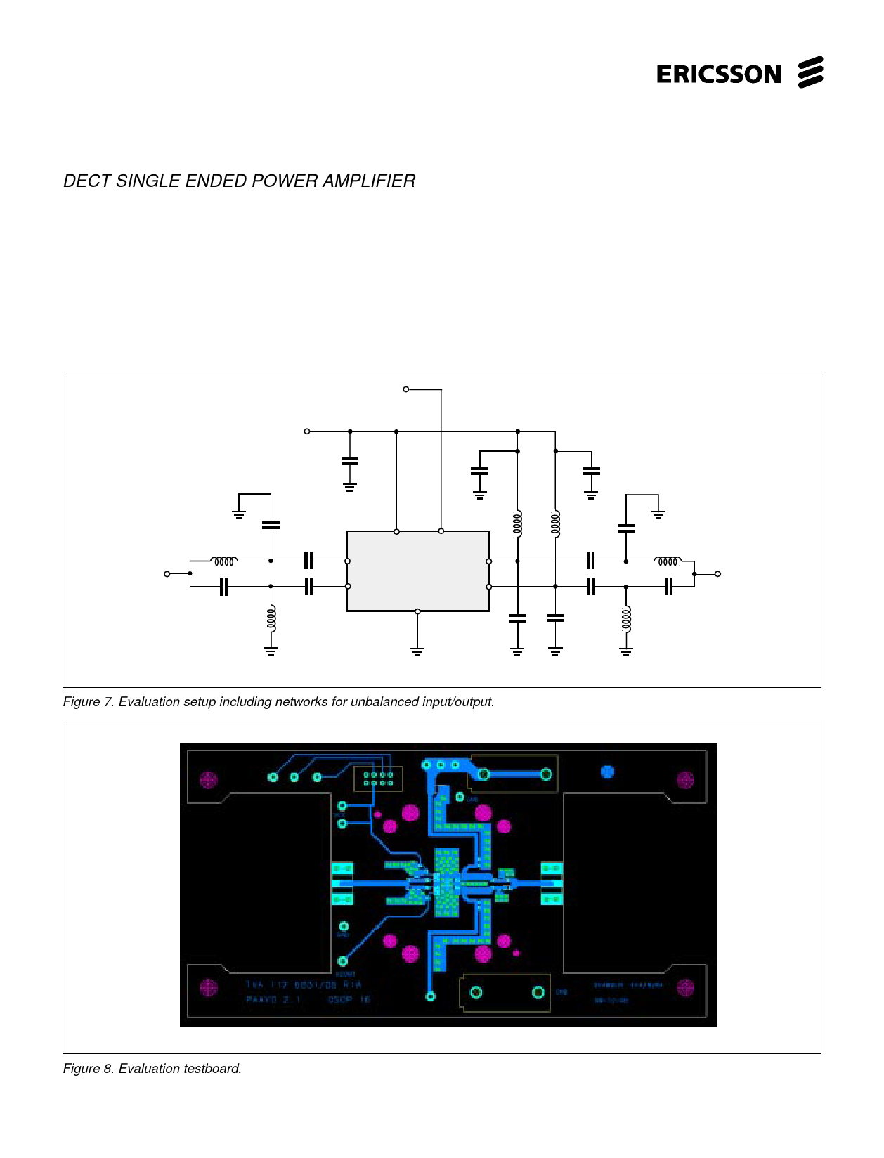
DECT SINGLE ENDED POWER AMPLIFIER
When used as a single ended power amplifier, please refer to fig.7 and the test board fig. 8.
The 50 Ω source impedance is converted to 50 Ω differential with an LC-CL structure. Two series capacitors AC-couples the signal
to the input of PBL403 09. Suitable value of the capacitors is 1 to 5 pF in order to compensate for series inductance of the PCB and
package. Input impedance of the PBL403 09 is 50 Ω differential.
The ideal collector load of the open collector RF output of PBL403 09 is about 11 Ω per side. A matching and combination network to
50 Ω single ended case is shown in fig. 7. A shunt capacitor (2.7 pF) transforms each output to 50 Ω. Both 50 Ω outputs are AC coupled
and then combined with an LC-CL structure to a 50 Ω single ended output.
PA-ON
Vcc
10n
100p
100p
input
1.5p
3.9n
1.5p
1.5p
1.5p
3.9n
PBL 403 09
68 68
n
n
33p
33p
2.7p
2.7p
GND
Figure 7. Evaluation setup including networks for unbalanced input/output.
1.1p
5.6n
1.1p
5.6n
output
Figure 8. Evaluation testboard.
4
Share Link: 