AZ10LVEL16VST Просмотр технического описания (PDF) - AZ Microtek
Номер в каталоге
Компоненты Описание
производитель
AZ10LVEL16VST Datasheet PDF : 8 Pages
| |||
AZ10LVEL16VS
AZ100LVEL16VS
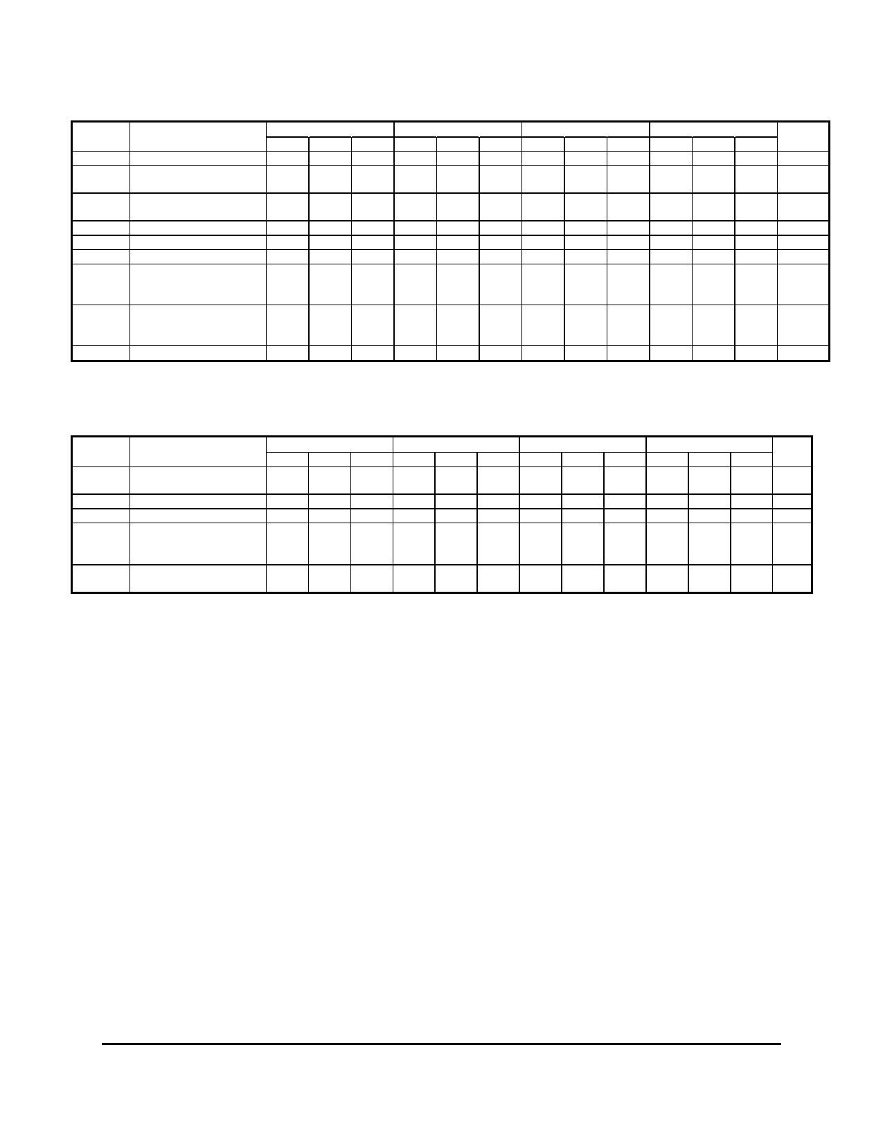
100K PECL DC Characteristics (VEE = GND, VCC = +5.0V)
Symbol
Characteristic
-40°C
0°C
25°C
85°C
Unit
Min Typ Max Min Typ Max Min Typ Max Min Typ Max
VOH
Output HIGH Voltage1,3 3915 3995 4120 3975 4045 4120 3975 4045 4120 3975 4045 4120 mV
VOL
Output LOW Voltage1,3
VCTRL = VBB2
3110
3380 3130
3320 3130 3225 3320 3130
3320 mV
VOL
Output LOW Voltage1,3
VCTRL = VCC
3820
4025 3865
4010 3865 3935 4010 3865
4010 mV
VIH
Input HIGH Voltage1
3820
4025 3865
4010 3865 3935 4010 3865
4010 mV
VIL
Input LOW Voltage1
3835
4120 3835
4120 3835
4120 3835
4120 mV
VBB
Reference Voltage1
3580
3740 3580
3740 3580
3740 3580
3740
V
Input HIGH Current
IIH
D, D¯
150
150
150
150
μA
VCTRL
40
40
40
40
Input LOW Current
IIL
D, D¯ -150
-150
-150
-150
μA
VCTRL 0.5
0.5
0.5
0.5
IEE
Power Supply Current
18
25
18
25
18
25
21
26
mA
1. For supply voltages other that 5.0V, use the ECL table values and ADD supply voltage value.
2. If VCTRL is Open Circuit, use the VOH (Max & Min) and VOL (VCTRL = VBB : Max only) limits.
3. Each output is terminated through a 50Ω resistor to VCC – 2V.
AC Characteristics (VEE = -3.0V to -5.5V; VCC = GND; VCTRL=VBB or VEE =GND; VCC = +3.0V to +5.5V; VCTRL=VBB)
Symbol
Characteristic
-40°C
0°C
25°C
85°C
Unit
Min Typ Max Min Typ Max Min Typ Max Min Typ Max
tPLH / tPHL
Input to
Output Delay
(DIFF)
(SE)
250
250
175 250 325 175 250 325 205 280 355 ps
125 250 375 125 250 375 155 280 405 ps
tSKEW
Duty Cycle Skew1 (Diff)
5
5
20
5
20
5
20 ps
VPP (AC) Minimum Input Swing2
150
150
150
150
mV
Common Mode Range3
VEE +
VCC - VEE +
VCC - VEE +
VCC - VEE +
VCC -
VCMR
VPP < 500mV 1.2
0.4 1.1
0.4 1.1
0.4 1.1
0.4 V
VPP ≥ 500mV 1.5
0.4 1.4
0.4 1.4
0.4 1.4
0.4
tr / tf
Output Rise/Fall Times Q
(20% - 80%)
100
260 100
260 100
260 100
260 ps
1. Duty cycle skew is the difference between a tPLH and tPHL propagation delay through a device.
2. VPP is the minimum peak-to-peak differential input swing for which AC parameters are guaranteed.
3. The VCMR range is referenced to the most positive side of the differential input signal. Normal operation is obtained if the HIGH level falls within
the specified range and the peak-to-peak voltage lies between VPP(min) and 1V.
November 2006 * REV - 2
www.azmicrotek.com
4
Share Link: 