AZ100EP16FETR1 Просмотр технического описания (PDF) - AZ Microtek
Номер в каталоге
Компоненты Описание
производитель
AZ100EP16FETR1
AZ Microtek

AZ100EP16FETR1 Datasheet PDF : 7 Pages
| |||
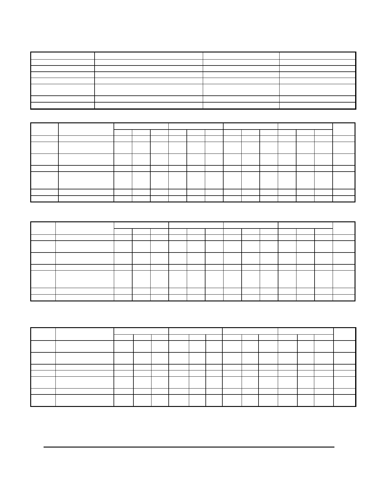
AZ100EP16FE
Absolute Maximum Ratings are those values beyond which device life may be impaired.
Symbol
Characteristic
Rating
Unit
VCC
PECL Power Supply (VEE = 0V)
0 to +4.5
Vdc
VI
PECL Input Voltage (VEE = 0V)
0 to +4.5
Vdc
VEE
ECL Power Supply (VCC = 0V)
-4.5 to 0
Vdc
VI
ECL Input Voltage (VCC = 0V)
-4.5 to 0
Vdc
IOUT
Output Current
--- Continuous
--- Surge
22
44
mA
TA
Operating Temperature Range
TSTG
Storage Temperature Range
-40 to +85
°C
-65 to +150
°C
100K ECL DC Characteristics (VEE = -3.0V to -3.6V, VCC = GND)
Symbol
Characteristic
-40°C
0°C
25°C
85°C
Unit
Min Typ Max Min Typ Max Min Typ Max Min Typ Max
VOH
Output HIGH Voltage1 -1095
VOL
Output LOW Voltage1
VCTRL = VREF
-1935
VOL
Output LOW Voltage1
VCTRL = VCC
-1140
-890 -1035
-1745 -1905
-950 -1120
-870 -1000 -920 -840 -940
-1715 -1885 -1790 -1695 -1830
-930 -1100 -1005 -910 -1055
-760 mV
-1640 mV
-865 mV
VREF
Reference Voltage
-1700
-1500 -1700
-1500 -1700
-1500 -1700
-1500 mV
Input HIGH Current
IIH
D, D¯
80
80
80
80
µA
VCTRL
400
400
400
400
IIL
Input LOW Current
0.5
0.5
0.5
0.5
µA
IEE
Power Supply Current
20
26
35
21
27
36
21
28
36
22
31
38
mA
1. Each output is terminated through a 180Ω resistor to VEE.
100K LVPECL DC Characteristics (VEE = GND, VCC = +3.3V)
Symbol
Characteristic
-40°C
0°C
25°C
85°C
Unit
Min Typ Max Min Typ Max Min Typ Max Min Typ Max
VOH
Output HIGH Voltage1,2 2205
VOL
Output LOW Voltage2
VCTRL = VREF
1365
VOL
Output LOW Voltage2
VCTRL = VCC
2160
2410 2265
1555 1395
2350 2180
2430 2300 2380 2460 2360
1585 1415 1510 1605 1470
2370 2200 2295 2390 2245
2540 mV
1660 mV
2435 mV
VREF
Reference Voltage
1600
1800 1600
1800 1600
1800 1600
1800 mV
Input HIGH Current
IIH
D, D¯
80
80
80
80
µA
VCTRL
400
400
400
400
IIL
Input LOW Current
0.5
0.5
0.5
0.5
µA
IEE
Power Supply Current
20
26
35
21
27
36
21
28
36
22
31
38
mA
1. For supply voltages other that 3.3V, use the ECL table values and ADD supply voltage value.
2. Each output is terminated through a 180Ω resistor to VEE.
AC Characteristics (VEE = -3.0 to -3.6V, VCC = GND, VCTRL=VREF or VEE = GND, VCC = +3.0V to +3.6V, VCTRL=VREF )
Symbol
Characteristic
-40°C
0°C
25°C
85°C
Unit
Min Typ Max Min Typ Max Min Typ Max Min Typ Max
fmax
Maximum Toggle
Frequency5
>6
>6
>6
>6
GHz
tPLH / tPHL
Input to Output
Delay
(Diff)
(SE)
100
150 240
155
100 150 240 100 150 240
155
155
120 170 280
175
ps
tSKEW
Duty Cycle Skew1 (Diff)
4
20
4
15
4
15
4
15
ps
Vpp
Minimum Input Swing2
150
150
150
150
mV
VCMR
Common Mode Range3
VEE +
2.0
VCC
VEE +
2.0
VCC
VEE +
2.0
VCC
VEE +
2.0
VCC
V
Av
Small Signal Gain4
28
dB
tr / tf
Output Rise/Fall Times Q
(20% - 80%)
130
130
130
130
ps
1. Duty cycle skew is the difference between a tPLH and tPHL propagation delay through a device.
2. VPP is the minimum peak-to-peak differential input swing for which AC parameters are guaranteed.
3. The VCMR range is referenced to the most positive side of the differential input signal. Normal operation is obtained if the HIGH level falls within the
specified range and the peak-to-peak voltage lies between VPP(min) and 1V. The lower end of the VCMR range varies 1:1 with VEE and is equal to VEE + 2V.
4. Differential input, differential output. 180Ω to VEE on Q/Q¯ outputs with 50Ω AC coupled load.
5. See Figure 2.
March 2002 * REV - 4
www.azmicrotek.com
2
Share Link: