ATS278-PL-B Просмотр технического описания (PDF) - Anachip Corporation
Номер в каталоге
Компоненты Описание
производитель
ATS278-PL-B Datasheet PDF : 6 Pages
| |||
Two Phase Hall Effect Latch With FG Output
ATS278
Absolute Maximum Ratings
Characteristics
Supply voltage
Reverse VCC Polarity Voltage
Magnetic flux density
Continuous
Output “on” current
Hold
Peak (Start Up)
Sink current of FG
Operating temperature range
Storage temperature range
Package Power Dissipation
Symbol
VCC
VRCC
B
Ic
IFG
Ta
Ts
PD
Electrical Characteristics ( Ta=+25°C )
Values
Unit
20
V
-20
V
Unlimited
0.4
0.5
A
0.7
40
mA
-20~+85
°C
-65~+150
°C
550
mW
Characteristic
Symbol
Conditions
Min Typ Max Unit
Supply Voltage
VCC
3.5 ---- 20
V
Output Saturation Voltage
Vce(sat) Vcc=14V, IL=300mA
---- 300 800 mV
Output Zener Breakdown
Vz*
46
V
Output Leakage Current
Icex
Vce=14V, Vcc=14V
---- <0.1 10 µA
Supply Current
Icc
Vcc=20V, Output Open
---- 16 25 mA
Output Rise Time
tr
Vcc=14V, RL=820Ω,
CL=20pF (Test Circuit)
---- 3.0 10 µs
Output Falling Time
tf
Vcc=14V, RL=820Ω,
CL=20pF (Test Circuit)
---- 0.3 1.5
µs
Switch Time Differential
∆t
Vcc=14V, RL=820Ω,
CL=20pF (Test Circuit)
---- 3.0 10 µs
FG saturation voltage
VFG Vcc=14V, IL=20 mA
---- 200 700 mV
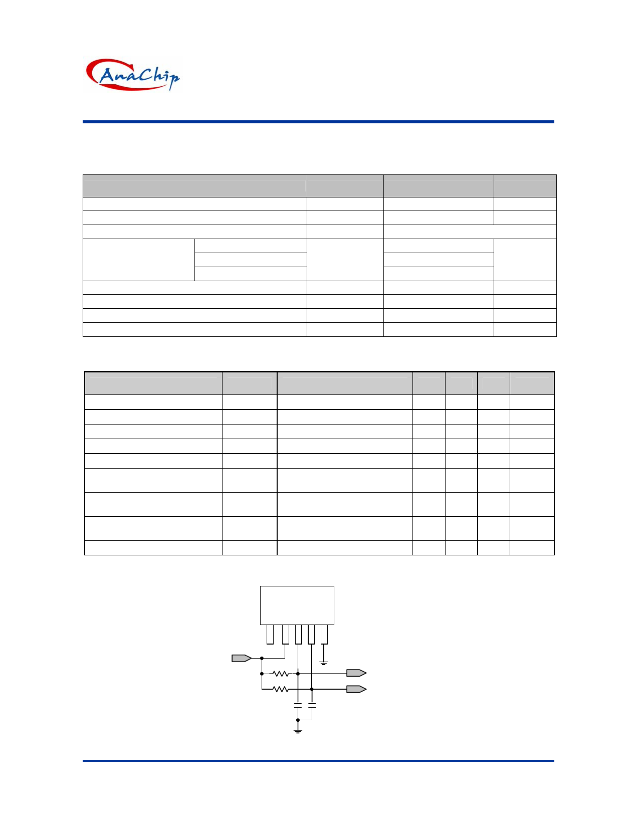
*Note: The Vz may vary with the inductance/resistance of DC Fan. In order to reduce the risk of dynamic operation, the capacitor/
resistor is recommended to add below the DO/DOB as Application Circuit (on page 1).
278
RL1 = RL2 = 820 Ω
CL1 = CL2 = 20 pf
1 2345
14V
RL1
RL2
DO
DOB
CL1
CL2
Anachip Corp.
www.anachip.com.tw
( Test circuit )
3/6
Rev. 1.0 Oct 4, 2005
Share Link: 