AT27C256R-70JU Просмотр технического описания (PDF) - Atmel Corporation
Номер в каталоге
Компоненты Описание
производитель
AT27C256R-70JU Datasheet PDF : 13 Pages
| |||
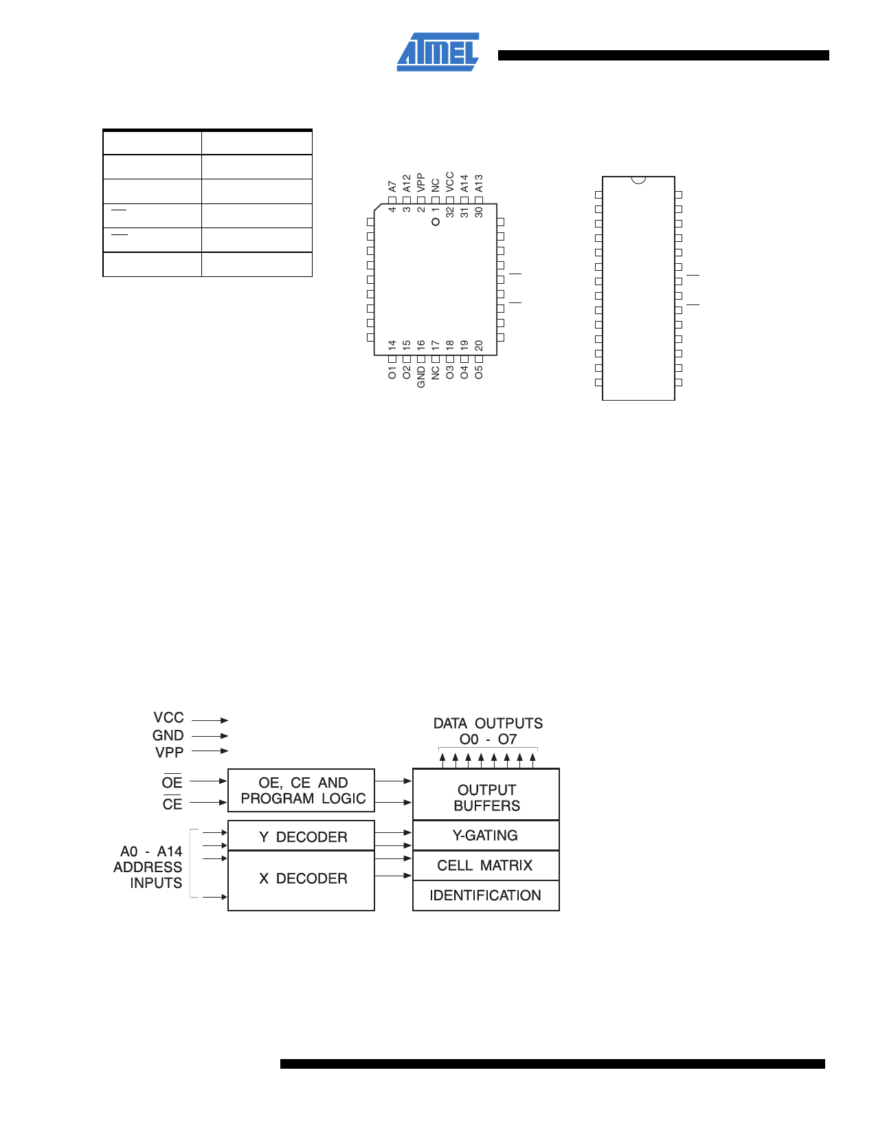
2. Pin configurations
Pin name
A0 - A14
O0 - O7
CE
OE
NC
Function
Addresses
Outputs
Chip enable
Output enable
No connect
32-lead PLCC
Top view
A6 5
A5 6
A4 7
A3 8
A2 9
A1 10
A0 11
NC 12
O0 13
29 A8
28 A9
27 A11
26 NC
25 OE
24 A10
23 CE
22 O7
21 O6
Note:
PLCC package pins 1
and 17 are “don’t
connect”
28-lead PDIP
Top view
VPP 1
A12 2
A7 3
A6 4
A5 5
A4 6
A3 7
A2 8
A1 9
A0 10
O0 11
O1 12
O2 13
GND 14
28 VCC
27 A14
26 A13
25 A8
24 A9
23 A11
22 OE
21 A10
20 CE
19 O7
18 O6
17 O5
16 O4
15 O3
3. System considerations
Switching between active and standby conditions via the chip enable pin may produce transient voltage excursions. Unless
accommodated by the system design, these transients may exceed datasheet limits, resulting in device non-conformance.
At a minimum, a 0.1µF, high-frequency, low inherent inductance, ceramic capacitor should be utilized for each device. This
capacitor should be connected between the VCC and ground terminals of the device, as close to the device as possible.
Additionally, to stabilize the supply voltage level on printed circuit boards with large EPROM arrays, a 4.7µF bulk electrolytic
capacitor should be utilized, again connected between the VCC and ground terminals. This capacitor should be positioned as
close as possible to the point where the power supply is connected to the array.
Figure 3-1. Block diagram
2
Atmel AT27C256R
0014O–EPROM–10/11
Share Link: 