25F1024AN Просмотр технического описания (PDF) - Atmel Corporation
Номер в каталоге
Компоненты Описание
производитель
25F1024AN Datasheet PDF : 20 Pages
| |||
AT25F1024A
The Ready/Busy status of the device can be determined by initiating a RDSR instruction. If Bit 0
= 1, the program cycle is still in progress. If Bit 0 = 0, the program cycle has ended. Only the
RDSR instruction is enabled during the program cycle.
A single Program instruction programs 1 to 256 consecutive bytes within a page if it is not write
protected. The starting byte could be anywhere within the page. When the end of the page is
reached, the address will wrap around to the beginning of the same page. If the data to be pro-
grammed are less than a full page, the data of all other bytes on the same page will remain
unchanged. If more than 256 bytes of data are provided, the address counter will roll over on the
same page and the previous data provided will be replaced. The same byte cannot be repro-
grammed without erasing the whole sector first. The AT25F1024A will automatically return to the
write disable state at the completion of the Program cycle.
Note:
If the device is not write enabled (WREN), the device will ignore the Write instruction and will
return to the standby state, when CS is brought high. A new CS falling edge is required to re-ini-
tiate the serial communication.
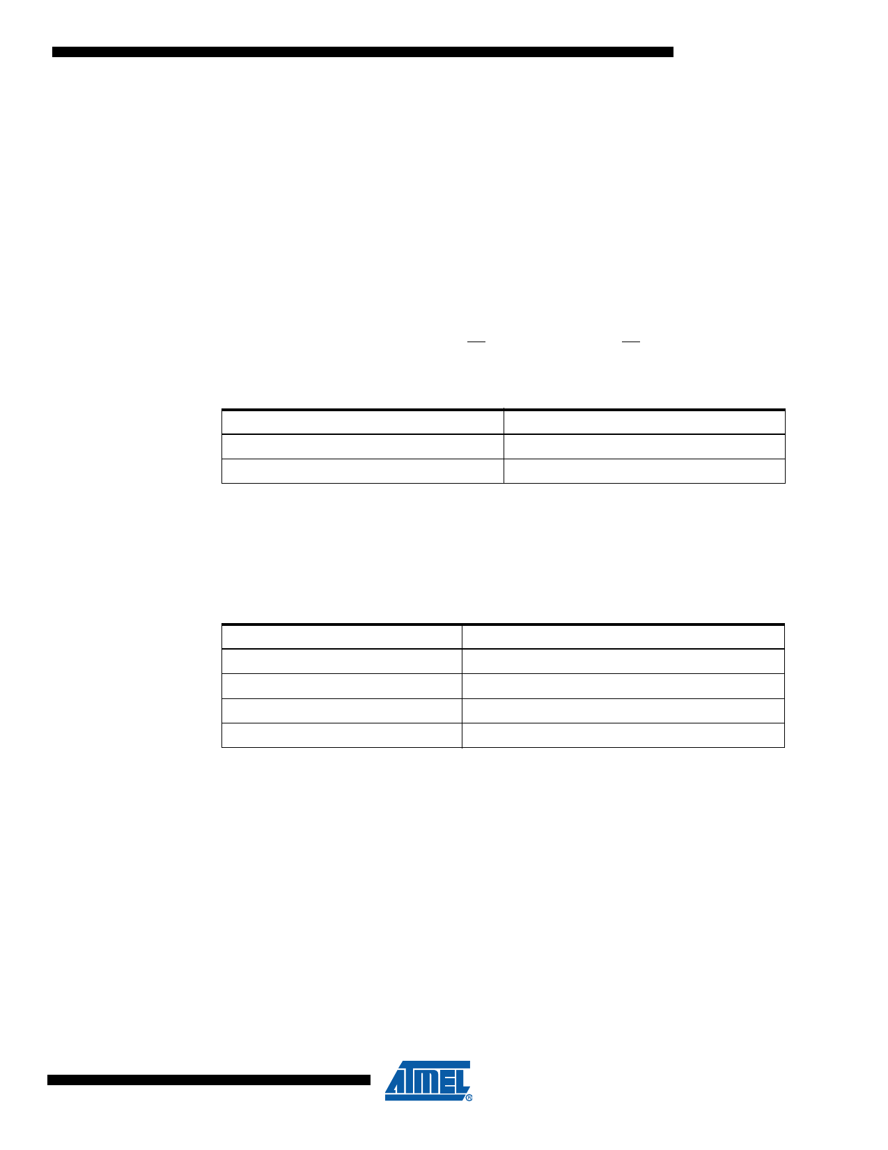
Table 2-6.
Address Key
Address
AN
Don’t Care Bits
AT25F1024A
A16 – A0
A23 – A17
SECTOR ERASE (SECTOR ERASE): Before a byte can be reprogrammed, the sector which
contains the byte must be erased. In order to erase the AT25F1024A, two separate instructions
must be executed. First, the device must be write enabled via the WREN instruction. Then the
Sector Erase instruction can be executed.
Table 1. Sector Addresses
Sector Address
000000 to 007FFF
008000 to 00FFFF
010000 to 017FFF
018000 to 01FFFF
AT25F1024A Sector
Sector 1
Sector 2
Sector 3
Sector 4
The Sector Erase instruction erases every byte in the selected sector if the sector is not locked
out. Sector address is automatically determined if any address within the sector is selected. The
Sector Erase instruction is internally controlled; it will automatically be timed to completion. Dur-
ing this time, all commands will be ignored, except RDSR instruction. The AT25F1024A will
automatically return to the write disable state at the completion of the Sector Erase cycle.
CHIP ERASE (CHIP ERASE): As an alternative to the Sector Erase, the Chip Erase instruction
will erase every byte in all sectors that are not locked out. First, the device must be write enabled
via the WREN instruction. Then the Chip Erase instruction can be executed. The Chip Erase
instruction is internally controlled; it will automatically be timed to completion. The Chip Erase
cycle time typically is 3.5 seconds. During the internal erase cycle, all instructions will be ignored
except RDSR. The AT25F1024A will automatically return to the write disable state at the com-
pletion of the Chip Erase cycle.
11
3346G–SFLSH–7/07
Share Link: 