AS3902 Просмотр технического описания (PDF) - austriamicrosystems AG
Номер в каталоге
Компоненты Описание
производитель
AS3902 Datasheet PDF : 14 Pages
| |||
ISM 433 MHz ASK Transmitter – Preliminary Data Sheet
AS3902
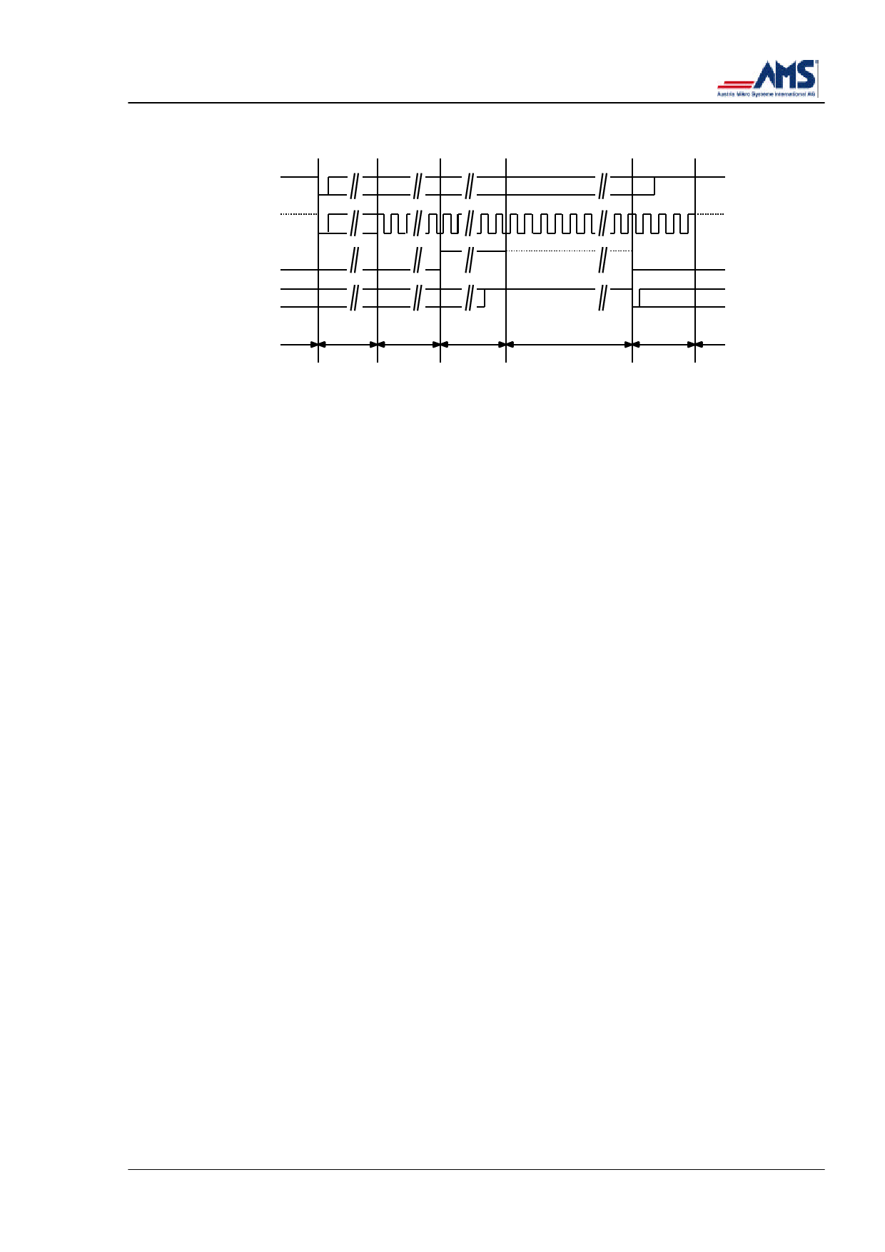
open
SW
closed
CLK/NWUP
NRES/PD
P2
standby startup 32 clocks 16 clocks
transmit
4 clocks standby
Figure 3:
µC interface timing for a transmission cycle.
Note:
The dashed lines indicate weak high or low state when the CLK/NWUP or NRES/PD output of the AS3902 is disabled (in
high-resistive Z state) and pulled “H“or “L“by the internal pull-up device or by the µC via a resistor. These weak states can be
overridden by the AS3902 if the respective outputs are enabled. Whenever a line is pulled via an external resistor, however,
this should override the internal pull-up devices of the AS3902.
1.5.1 Interface Description
It is assumed that the µC remains in low power standby mode as long as the P2 pin is kept “L“
and no clock cycles are applied.
Standby: During standby (default after VCC-on) the XTAL oscillator is turned off and AS3902
holds the µC in a reset state:
The AS3902 NRES/PD pin is active and set to “L“, holding the µC in reset state. In standby
mode the AS3902 internal NRES/PD pull-up is disabled and does not drain current from the
supply.
The AS3902 CLK/NWUP output is disabled, (in high resistive “Z“state) and internally pulled up
to “H“.
(Re)starting the transmitter: Closing the push button (giving a falling edge on CLK/NWUP-
CLOCK line) starts up the AS3902. It turns on its XTAL oscillator and after the oscillator start
up phase it turns the CLK/NWUP pin to active (CMOS level) mode and provides a clock to the
µC.
After a delay of 32 µC clock cycles the NRES/PD pin of the AS3902 is set to “H“for 16 clock
cycles. The transmitter is now in active mode. The NRES/PD acts in AS3902 active mode as
an input waiting for a “L“to trigger the transmission of the transmitter to standby mode.
During this active mode the µC can turn on and off the synthesizer and driving amplifier in the
rhythm of the data on the TX - P1 (Serial data out) line and transmit ASK data.
Bringing the transmitter to standby: After completing the transmission, the µC may indicate
“end of transmission“by setting P2 (not end of transmit) to “L“and pulls the NRES/PD-
NRESET line to “L“. Sensing this, 4 clock cycles later the AS3902 will switch back to standby
mode, disabling the CLK/NWUP output, setting the active NRES/PD pin to “L“and turning off
the XTAL oscillator.
Repetitive transmission: If the button is still pressed when the µC indicates “end of transmis-
sion“by setting P2 pin to “L“and pulling the NRES/PD-NRESET line to “L“, 4 µC clock periods
later the sequence above will be repeated starting from the 32 clock delay period.
Due to the sophisticated tri-state - active/inactive pull-up configuration of the NRES/PD pin the
AS3902 does not drain current during its standby periods.
Rev. A7, December 2000
Page 5 of 14
Share Link: 