AS1910R-T Просмотр технического описания (PDF) - austriamicrosystems AG
Номер в каталоге
Компоненты Описание
производитель
AS1910R-T
austriamicrosystems AG

AS1910R-T Datasheet PDF : 15 Pages
| |||
AS1910 - AS1915
Data Sheet - Detailed Description
8 Detailed Description
The AS1910 - AS1915 supervisory circuits were designed to generate a reset when one of the two monitored supply
voltages falls below its factory-trimmed trip threshold (see VTH on page 4 and VTH2 on page 4), and to maintain the
reset for a minimum timeout period (see tRP on page 5) after all supplies have stabilized.
The integrated watchdog timer (see Watchdog Input on page 10) helps mitigate against bad programming code or
clock signals, and/or poor peripheral response. An active-low manual reset input (see Manual Reset Input on page 10)
allows for an externally activated system reset.
RESET/RESETN
Whenever one of the monitored voltages falls below its reset threshold, the RESET output (AS1910, AS1912, AS1913,
AS1915) asserts low or the RESETN output (AS1911, AS1914) asserts high. Once all monitored voltages have stabi-
lized, an internal timer keeps the reset asserted for the reset timeout period (tRP). After the tRP period, the RESET or
RESETN output return to their original state (see Figure 10).
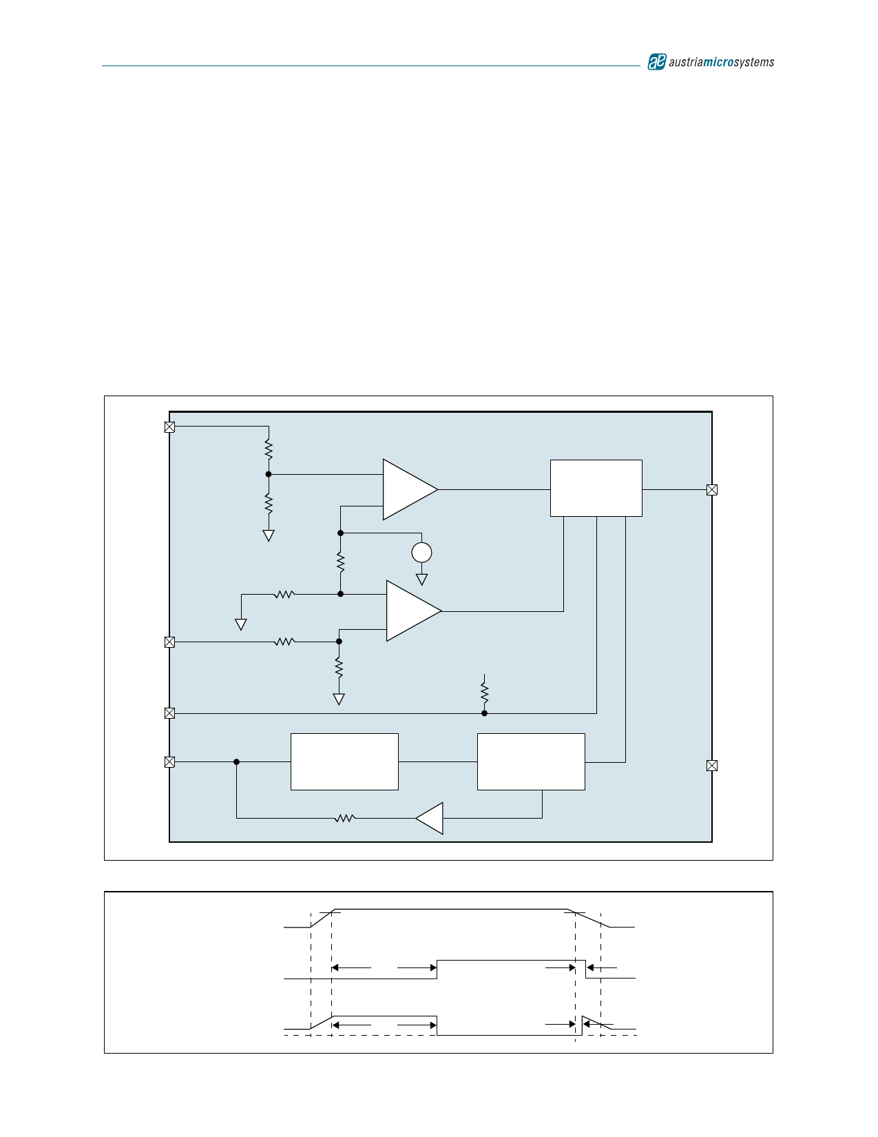
Figure 9. Functional Diagram of VCC Supervisory Application
6
AS1913/AS1914/AS1915
VCC
0.63V
+
–
1.26V
Reset Timeout
Delay Generator
1
RESETN/
RESET
5
VCC2
3
MRN
4
WDI
Watchdog Transition
Detector
VCC
Watchdog
Timer
2
GND
Figure 10. Reset Timing Diagram
VCC
1V
RESETN
RESET
GND
VTH
tRP
tRP
VTH
1V
tRD
tRD
www.austriamicrosystems.com
Revision 1.00
8 - 15
Share Link: