AS1152 Просмотр технического описания (PDF) - austriamicrosystems AG
Номер в каталоге
Компоненты Описание
производитель
AS1152 Datasheet PDF : 15 Pages
| |||
AS1152
Data Sheet
austriamicrosystems
Cables and Connectors
Supported transmission media include printed circuit board traces, backplanes, and cables.
! Use cables and connectors with matched differential impedance (typically 100Ω) to minimize impedance mis-
matches.
! Balanced cables such as twisted pair offer superior signal quality and tend to generate less EMI due to magnetic
field canceling effects. Balanced cables pick up noise as common mode, which is rejected by the LVDS receiver.
! Avoid the use of unbalanced cables such as ribbon cable or simple coaxial cable.
Board Layout
The device should be placed as close to the interface connector as possible to minimize LVDS trace length.
! Keep the LVDS and any other digital signals separated from each other to reduce crosstalk.
! Use a four-layer PC board that provides separate power, ground, LVDS signals, and input signals.
! Isolate the input LVDS signals from each other and the output LVCMOS/LVTTL signals from each other to prevent
coupling.
! Separate the input LVDS signals from the output signals planes with the power and ground planes for best results.
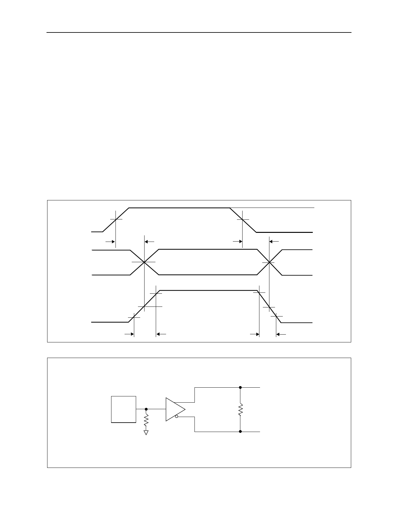
Figure 18. Driver Propagation Delay and Transition Time Waveforms
INx
OUTx-
OUTx+
1.5V
tPLHD
0 Differential
1.5V
tPHLD
0
VOH
VOL
20%
80%
0
tTLH
80%
VDIFF = (VOUTx+) - (VOUTx-)
0
20%
tTHL
Figure 19. Driver Propagation Delay and Transition Time Test Circuit
Generator
INx
50Ω
OUTx+
RL
OUTx-
www.austriamicrosystems.com
Revision 1.00
11 - 15
Share Link: 