APX9270 Просмотр технического описания (PDF) - Anpec Electronics
Номер в каталоге
Компоненты Описание
производитель
APX9270 Datasheet PDF : 17 Pages
| |||
APX9270
Function Description
Variable Speed Control
The APX9270 is designed with a variable speed control-
ler which has two external input signals, a temperature
signal sensed by a thermistor and an external PWM
signal.
Temperature Speed Control
Using thermistor get temperature to make SET pin voltage.
The fan’s speed is decided by comparing OSC and
SET pin voltage. In addition, the lowest drive duty is
set by comparing the OSC oscillating voltage and MIN
pin voltage (only for temperature speed control side).
Temperature control system works by comparing the
voltage of SET and OSC. When SET voltage is lower than
OSC voltage, one OUT pulled high and another OUT
pulled low. On the contrary, when SET voltage is higher
than OSC voltage, upper side transistors are OFF;
meanwhile, the coil current re-circulates lower side
transistor. Therefore, with decreasing SET voltage, the
output ON-Duty will be increasing, which results in the
increasing of the coil current and motor rotation speed.
External PWM Speed Control
the fan is locked. Connecting the capacitor from CT pin to
GND determines the shutdown time and restart time. As
the fan is locked, the charge/discharge circuit will charge
the CT capacitor to 3.6V by a 2.2µA source current for a
locked detection time, and then the circuit will switch the
capacitor to discharge. During the discharging interval,
the output drivers are switched off until the CT voltage is
discharged to 1.6V by a 0.22µA sink current, and the
circuit will switch the capacitor to charge. In the charging
interval, the IC enters the restart time; one output is high
and another is low, which makes a torque for fan rotation
until the CT voltage is charged to 3.6V by a 2.2µA source
current. If the locked condition still remains, the charge/
discharge process will be recurred until the locked
condition is released (see Figure 2: Lock/Auto Restart
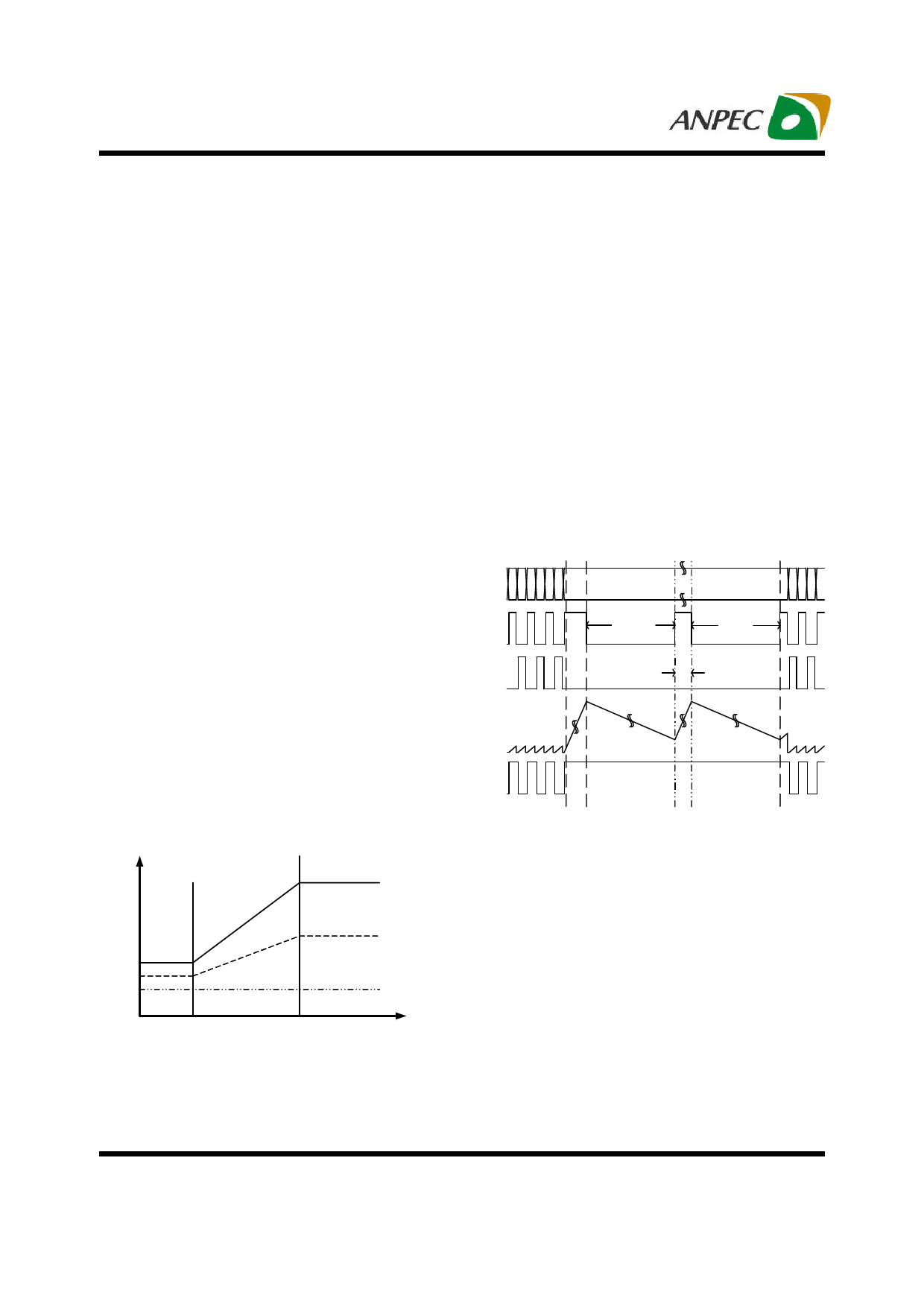
Waveform).
VIN-
VIN+
VOUT2
TOFF
TOFF
VOUT1
TON
This is a pin for the direct PWM speed control. PWM pin
input is pulled down to GND when it is not used. The
VCT
minimum duty is performed by R6 and R7 resistances
(see Typical Application Circuit). R7 is left open if you
want to stop rotation when PWM duty is 0%.
VFG
(see Figure 1: Rotation Control Curve)
OUT -DUTY(%)
External PWM-Duty
Lock Lock
Detection
Release
Figure 2: Lock/Auto Restart Waveform
Duty 100%
Duty 50 %
Duty 0%
TA (oC)
Figure 1: Rotation Control Curve
Lockup Protection and Automatic Restart
The APX9270 provides the lockup protection and auto-
matic restart functions to prevent the coil burnout while
Current Limit
The APX9270 includes both internal and external current
limiters. External current limiter value is programmed by
R which is located between VCC pin and VM pin. The
L
external current limiter works when the voltage difference
between both sides of RL raises to be 0.48V or higher.
For example, the RL=0.5Ω, the external current limiter
value is fixed and internally set at 960mA. The internal
current limiter value is different in rotation mode and lock
mode. It is 1.2A in rotation mode, but it decreases to 0.6A
in lock mode. This feature can reduce power consump-
tion while the fan is locked. In general application, it is
Copyright © ANPEC Electronics Corp.
10
Rev. A.3 - Jun., 2008
www.anpec.com.tw
Share Link: 