APA2175O Просмотр технического описания (PDF) - Anpec Electronics
Номер в каталоге
Компоненты Описание
производитель
APA2175O Datasheet PDF : 19 Pages
| |||
APA2175
Function Description
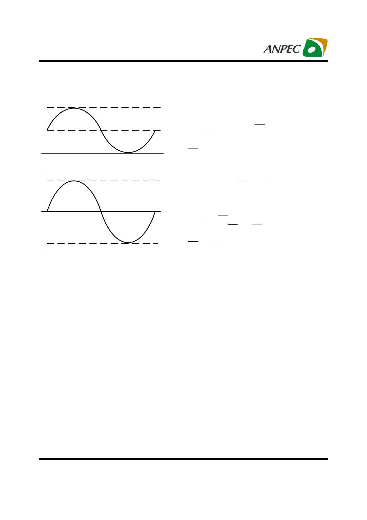
Line Driver Operation
VOUT
Conventional Line Driver
VOUT
VDD
VDD/2
0
VDD
0
VSS
Cap-free Line Driver
Figure 1. Cap-free Line Driver’s Operation
Shutdown Function
In order to reduce power consumption while not in use,
the APA2175 contains two shutdown controllers to allow
either channel being independent and externally turns off
the amplifier bias circuitry. LSD controls the left channel
and RSD controls the right channel. This shutdown fea-
ture turns the amplifier off when logic low is placed on the
RSD and LSD pins for the APA2175. The trigger point be-
tween a logic high is 1.0V and logic low level is 0.35V. It is
recommended to switch between ground and the supply
voltage V to provide maximum device performance. By
DD
switching the both RSD and LSD pins to the low level, the
amplifier enters a low-consumption current circumstance,
charge pump is disabled, and I for the APA2175 is in
DD
shutdown mode. The charge pump is enabled once ei-
ther RSD or LSD pin is pulled to high. In normal operating,
the APA2175’s RSD and LSD pins should be pulled to a
high level to keep the IC out of the shutdown mode. The
RSD and LSD pins should be tied to a definite voltage to
avoid unwanted circumstance changes.
The APA2175’s line drivers use a charge pump to invert
the positive power supply (VDD) to negative power supply
(VSS), see figure1. The line drivers operate at this bipolar
power supply (VDD and VSS) and the outputs reference re-
fers to the ground. This feature eliminates the output ca-
pacitor that is using in conventional single-ended line
drive amplifier. Compare with the single power supply
amplifier, the power supply range has almost doubled.
Thermal Protection
The thermal protection circuit limits the junction tempera-
ture of the APA2175. When the junction temperature ex-
ceeds TJ=+150OC, a thermal sensor turns off the driver,
allowing the devices to cool. The thermal sensor allows
the driver to start-up after the junction temperature down
about 125OC. The thermal protection is designed with a
25OC hysteresis to lower the average T during continu-
J
ous thermal overload conditions, increasing lifetime of
the ICs.
Copyright © ANPEC Electronics Corp.
11
Rev. A.3 - Jul., 2010
www.anpec.com.tw
Share Link: 