AP3710P-G1 Просмотр технического описания (PDF) - BCD Semiconductor
Номер в каталоге
Компоненты Описание
производитель
AP3710P-G1 Datasheet PDF : 16 Pages
| |||
Data Sheet
LOW POWER PWM CONTROLLER FOR OFF-LINE ADAPTER
AP3710
Function Description (Continued)
2. VCC/Feedback Control
In Figure 14, an opto-coupler and secondary constant
voltage consists of voltage feedback network. Voltage
feedback loop consists of shunt regulator AZ431 and
FB/VCC terminal of AP3710. When load is heavy, the
voltage on VCC terminal will decrease to enlarge duty
cycle; on the contrary, if load drops, the voltage on
VCC will increase to reduce duty cycle.
5. Current Limit Control
The AP3710 employs current mode control to
improve transient response and voltage stability. In
Figure 3, the external inductor current through the
OUT pin is converted to a voltage by an internal
resistor, and this voltage will participate to control
duty cycle and peak inductor current.
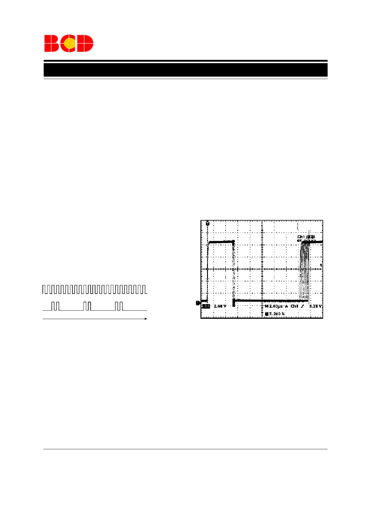
3. Skip Cycle Mode Operation
The AP3710 enters skip cycle mode when load power
drops below a given level, and this is performed by
sensing the VCC voltage level, i.e., the heavier load
power, the lower VCC voltage level. In normal
operation, the VCC terminal indicates a peak
inductance current under certain load power. If the
load power decreases, VCC voltage level increases to
ask for less peak current. When it reaches a
determined value, the IC prevents the current from
decreasing further down and starts to blank the output
pulses, the IC then enters the skip cycle mode
operation. Figure 16 is the sketch for the two operation
mode.
Normal
PWM
Waveform
Cycle Skip
Waveform
0
t
Figure 16. Skip Cycle and Normal PWM Waveform
4. Slope Compensation
The AP3710 is current mode PWM controller, and it
regulates peak inductance current by its current
control loop. It is known that a continuous conduction
mode SMPS may induce noise and harmonic
oscillation on current sense or feedback signal, and
this is especially serious when duty cycle exceeds
50%. The internal slope compensation of AP3710 can
improve power supply stability by increasing the
current slope.
6. Frequency Dithering
Frequency dithering is performed by periodically
spreading a single switching frequency into adjacent
frequency band, so the peak energy is spread. This
technique can improve EMI performance by reducing
both quasi peak and average EMI emissions.
Figure 17. Frequency Dither Influences
the Switching Cycle
Aug. 2008 Rev. 1. 3
BCD Semiconductor Manufacturing Limited
10
Share Link: 