AN1013 Просмотр технического описания (PDF) - STMicroelectronics
Номер в каталоге
Компоненты Описание
производитель
AN1013 Datasheet PDF : 13 Pages
| |||
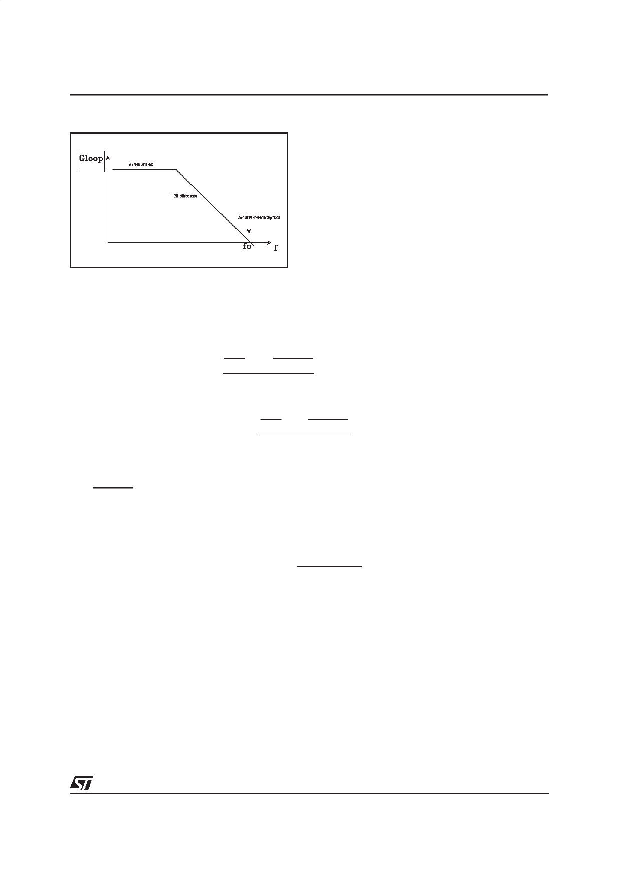
Figure 13
AN1013 APPLICATION NOTE
The loop gain of this configuration is the following (fig. 13)
The feedback works properly only if fo (unity-gain frequncy) is lower than the switching frequency fsw.
The optimum behaviour is obtained with fo ~ 0.7fsw. For example, with fsw =120Khz, the capacitance
C4 (pin 8 DIP20, pin 5 MW15) is about 4.7nF.
If the switching frequency is changed, the C4 capacitance can be changed too to fit the following for-
mula:
1
2 ⋅π
⋅
AV
⋅
R1
R1 + R2
Rp ⋅ C4
=
0.7
fsw
[12]
From [12] it is possible to calculate the value of C4 vs switching frequency fsw:
where:
C4
=
1
2⋅π
⋅
Av
⋅
R1
R1 + R2
Rp ⋅ 0.75 ⋅ Fsw
[13]
R1 = 30KΩ; R2 = 45KΩ;
Rp
=
R1⋅ R2
R1 + R2
=
18KΩ
Av = 100;
fsw : switching frequency
With these values in [13], it is possible to obtain the final formula of C4 vs fsw to be used:
C4 = 5.05E −4
F ⋅ 141.414hz
fsw
[14]
For example, with fsw =120Khz, with [14] C4 = 4.2nF.
A.1) Output LC filter dimensioning
The low pass filter placed after the switching stage is dimensioned to eliminate the high frequency PWM
waves and to feed the Audio signal to the loudspeaker.
The TDA7480/81 operate at a switching frequency of 120Khz, the LC low pass filter suggested in the ap-
plication circuit is a typical 2 pole Butterworth designed to have a cutoff frequency outside the Audio
band (fc = 30KHz).
This filter topology was chosen because it offers the feature to be maximally flat in the passband.
The filter frequency response will be flat only if it is properly loaded on the specified
loudspeaker impedance for example 8 ohm (fig.14),
9/13
Share Link: 